Chapter 8 Option CardsMS300
155
Grounded installation
You must ground the option cards as listed below when wiring. The ground terminal is included in
the option card package, as shown in Figure 8-20.
1. CMM-PD02
2. CMM-DN02
3. CMM-EIP02
4. CMM-EIP03
5. CMM-COP02
6. CMM-EC02
7. EMM-BPS02
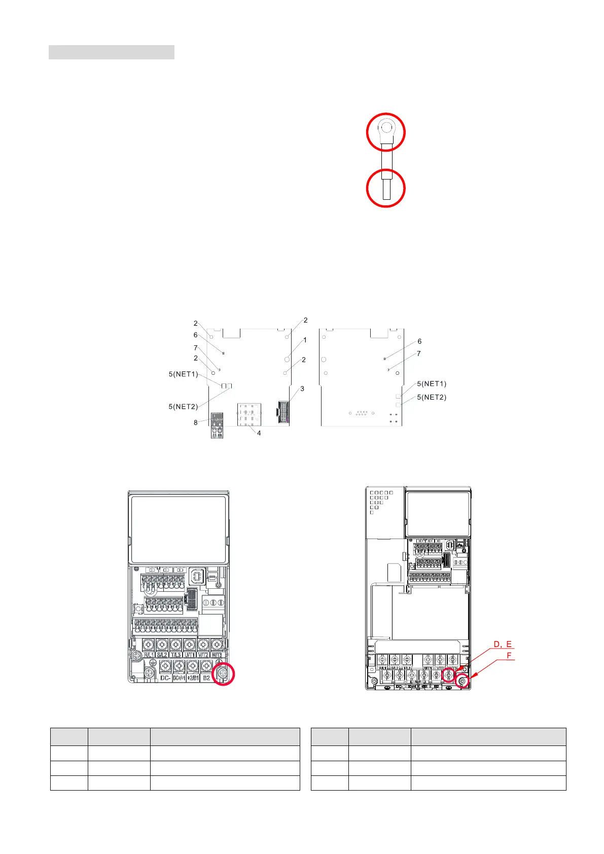
Installation of the ground terminal:
The B end of the grounding wire connects to the ground terminal block of the option card, as the
No.6 shows in Figure 8-21 (see Chapter 8 for the ground terminal block position of other option
cards). The A end of the grounding wire connects to the drive’s PE, as the circles show in Figure 8-
22 and Figure 8-23.
Figure 8-21
9 kg-cm/ (7.8 lb-in)/ (0.88 Nm)
20 kg-cm/ (17.4 lb-in)/ (1.96 Nm)
15 kg-cm/ (13.0 lb-in)/ (1.47 Nm)
25 kg-cm/ (21.7 lb-in)/ (2.45 Nm)
20 kg-cm/ (17.4 lb-in)/ (1.96 Nm)
20 kg-cm/ (17.4 lb-in)/ (1.96 Nm)
 Loading...


