EasyManua.ls Logo

Delta PCS100HV - Page 38

Delta PCS100HV
57 pages
To Next Page IconTo Next Page
To Previous Page IconTo Previous Page
Loading...
Installation Manual
31
Wiring Instructions
7. Digital Output 4-2
Dry Contact 4
(Max 24Vdc/10mA)
8. Digital Output 4-1
9. Digital Input 1-2
Wet Contact 1
(24Vdc/20mA)
10. Digital Input 1-1
11. Digital Input 2-2
Wet Contact 2
(24Vdc/20mA)
12. Digital Input 2-1
13. Digital Input 3-2
Wet Contact 3
(24Vdc/20mA)
14. Digital Input 3-1
15. REPO_2
Remote EPO, Wet Contact for customer,
Normal Close.
16. REPO_1
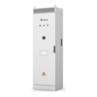
AD sample connector (CNR2)
The CNR2 connector is for the AD sampling connection. Take out the green 16-pin connector (CNR2)
from the accessory kit, and connect three prepared AWG 16 wires to pin 11~16 of this connector as
shown in the following figure.
The PIN1~PIN10 are reserved. And the PIN11~PIN16 are used for sensing the grid current for the
reverse power detection.
Figure 26. CNR2 Pin Assignment
Table 8: CNR2 Pin Assignment
Item
Pin Assignment
Notes
CNR2
1~10: NA
Reserved
11: IGR_2
From external current measurement
12: IGR_1
in 1
Pin 1

Other manuals for Delta PCS100HV

Related product manuals