Terminal Resistor
Terminal Resistor
120Ω(1/2W)
DATA+ to DATA-
120Ω(1/2W)
DATA+ to DATA-
RS485/USB
or
RS485/RS232
Data Format:
Baud rate: 9600, 19200 (default), or 38400
Data bits: 8
Stop bit: 1
Parity: N/A
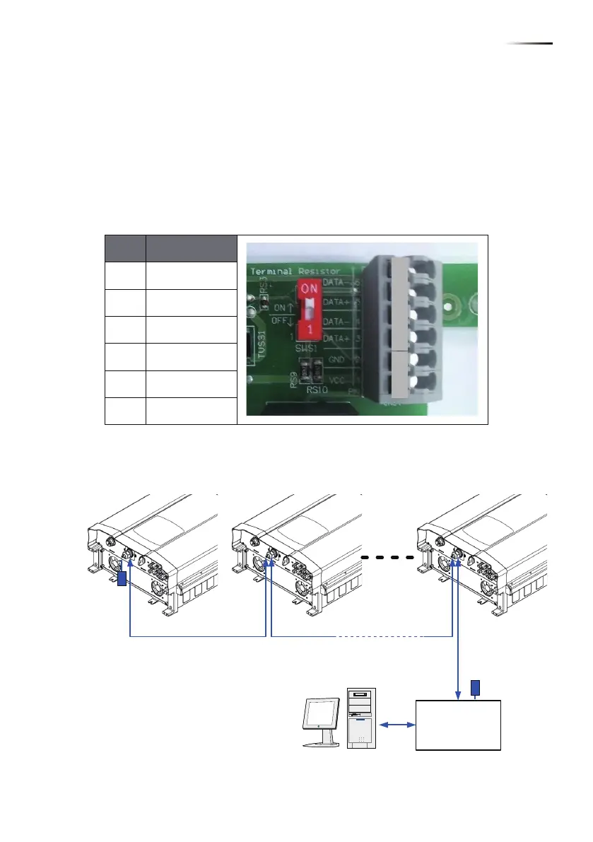
4.4.1. RS-485 Connection
The pin definition of RS-485 is shown in table 4-5. Different RS-485
connection needs different set up of the terminal resistor.
• When single inverter is installed, the terminal resistor on its communication
module should be switched ON.
• When multi-inverters in chain as shown in Figure 4-7, only the first and
last inverter’s terminal resistor must be switched ON.
Please refer to table 4-6 for the terminal resister setting.
Pin Function
1 VCC (+12V)
2 GND
3 DATA+
4 DATA-
5 DATA+
6 DATA-
Table 4-5 Definition of RS 485 pin
Figure 4-7 Multi-inverter connection illustration
1
2
3
4
5
6
21
Wiring
 Loading...