46
Inordertoconnectthedeviceelectrically,thefollowingproceduresmustbefollowed:
1.DCconnection:First,connectthePVmodulestringstotheDCdisconnectswitch(notincluded
inthescopeofdelivery).
2.ConnecttheDCdisconnectswitchtothesolarinverter(ensurecorrectpolarity).
3.ACconnection:Next,connecttheACconnectortothesolarinverterandthentothemains.
4.Beforeswitchingonthepower,checkallfeedersandconnectionsonelasttime.
5.CloseDCdisconnect.
6.ClosethecircuitbreakerontheACoutputside.
7.IncaseofsufcientPVvoltage(UPV>170V),thedevicenowgoesintothestart-upmode.
8.Inthecaseofanewinstallationthetimeanddatehavetobesetinsub-menuS(Setup)(see
page51,section7.3.7).
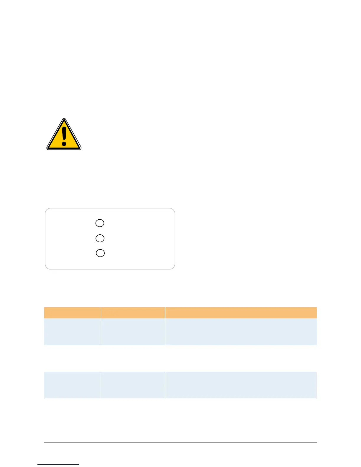
•LED(A),green:„Operation“displaysthe
operationalstate.
•LED(B),red:„EarthFault“displaysaninsula-
tionresistancefaultorPVgrounding(GND)
faultontheDCside.
•LED(C),yellow:„Failure“displaysexisting
faultsinternallyorexternallyandwhetherthe
networkfeed-inoperationhasbeeninter-
rupted.
6.10 LEDoperationandfaultdisplay
Threelight-emittingdiodes(LEDs),whichdisplaytheoperationalstateofthesolarinverter,areat-
tachedonthefront:
LEDStatus Operational state Explanation
green:<off>
red:<off>
yellow:<off>
Nightdisconnection.
Theinputvoltage(UPV)islowerthan100V.
Thesolarinverterisnotfeedingpowertothegrid.
green:<on>
red:<on>
yellow:<on>
Initialization.
Inputvoltages:
UPV:100Vto170V
(selftestongoing).
green:<ashes>
red:<off>
yellow:<off>
Input-andgrid
monitoring.
Startingconditionsaretested.
green:<on>
red:<off>
yellow:<off>
Feed-inoperation.
Normaloperationalstate:
UPV:170Vto540V.
Allunoccupiedconnectorsandinterfacesmustbeshutoffairtightusingthede-
liveredseals.
Operation (A)
Earth Fault (B)
Failure (C)
 Loading...