12
OPERATING CONTROLS A N D ADJUSTMENTS
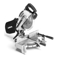
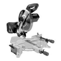
Fig. 15
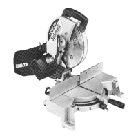
Fig. 16
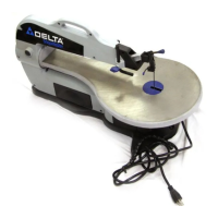
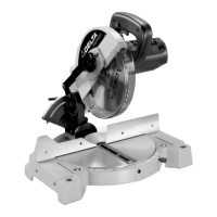
Fig. 17
STARTING A N D
STOPPING MACHINE
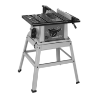
To st art the machine, depress switch trigger (A) Fig. 15.
To stop the machine, release the switch trigger .
This saw is equipped with an automatic electric blade
brake. As soon as the switch trigger (A) Fig. 15, is re-
leased, the electric brake is activated and stop s the
blade in seconds.
DANGER: A TURNING SAW BLADE CAN BE DANGER-
OUS. AFTER COMPLETING CUT, RELEASE SWITCH
TRIGGER (A) FIG. 15, T O ACTIVATE BLADE BRAKE.
KEEP CUTTINGHEAD DOWN UNTIL BLADE HAS COME
TO A COMPLETE STO P.
W ARNING: THE TORQUEDEVELOPED DURING BRAK-
ING M AY LOOSEN THE ARBORSCREW. THEARBOR
SCREWSHOULD BE CHECKED PERIODICALLY A N D
TIGHTENED IF NECESSARY.
LOCKING SWITCH
IN THE OFF POSITION
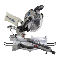
IMPORTANT:W e suggest that when the miter saw is not
in use, the switch be locked in the OFF position using a
p adlock (B), as shown in Fig. 16. A vailable as an acces -
sory from Delt a is the 50-325 p adlock, shown at (B).
R O TATING TABLE
FOR MITER CUTTING
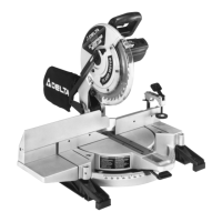
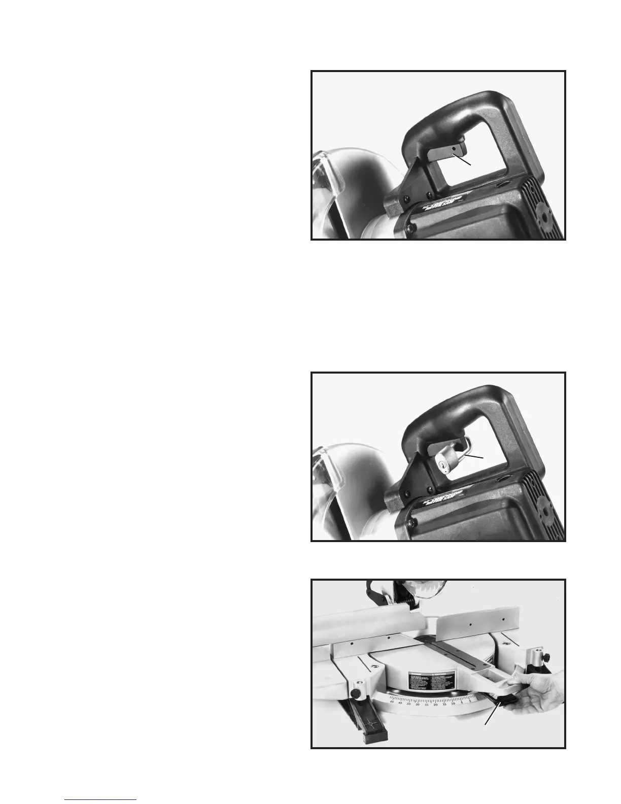
1. Your compound miter saw will cut any angle from a
straight 90 degree cut to 47 degrees right and lef t. Simply
depress t able lock lever (A) Fig. 17, and rot ate the t able
to the desired angle. Then release t able lock lever (A).
2. IMPORTANT:Table lock lever (A) Fig. 17, must be
depressed when rotating the t able. When lock lever (A)
is not depressed, the t able is in the locked position.
A
B
A
 Loading...