6
ASSEMBLY INSTRUCTIONS
W ARNING: F O R YOUR O W N SAFETY, DO NOT CONNECT THE MITER S AW TO THE
POWER SOURCE UNTIL T H E MACHIN E IS COMPLETELY ASSEMBLED AND YOU
HAVE READ AND UNDERSTO O D THE ENTIRE OWNERSMANUAL.
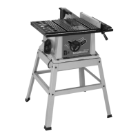
Fig. 4
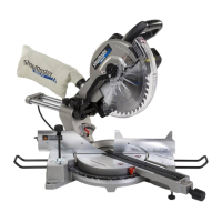
Fig. 5
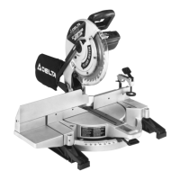
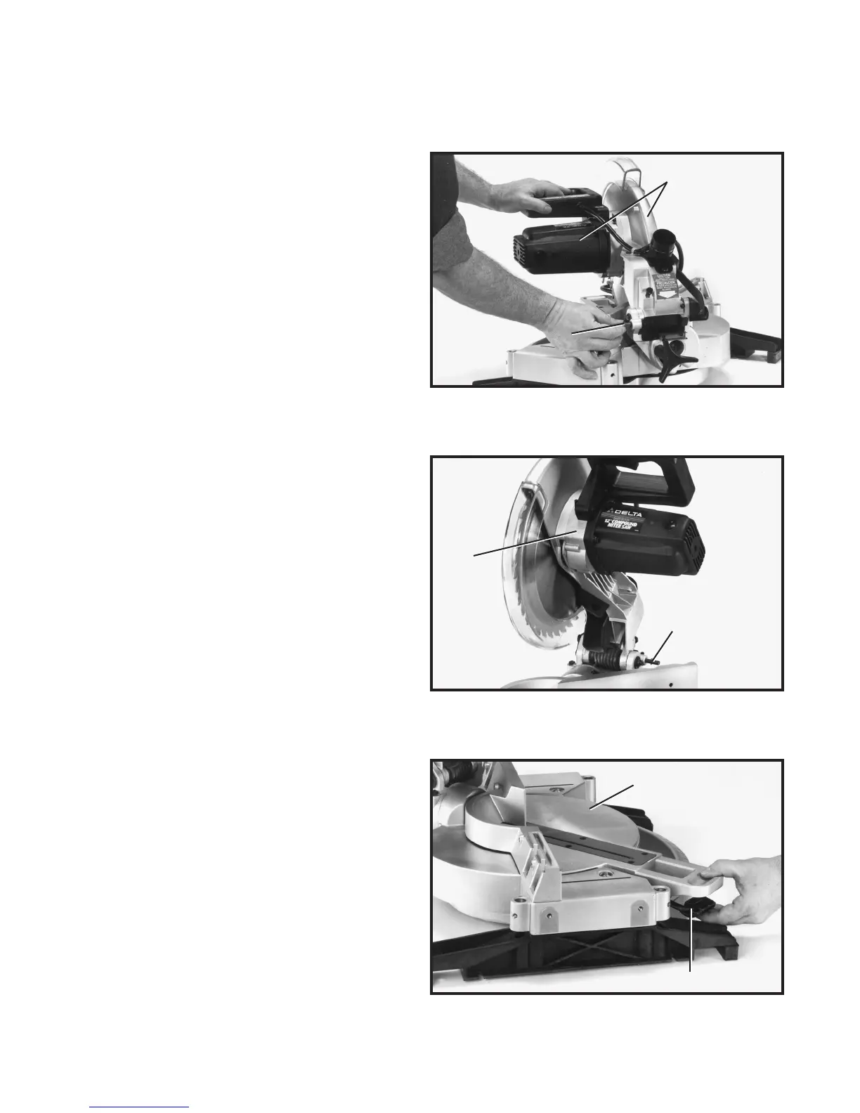
Fig. 6
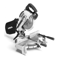
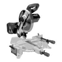
MOVING CUTTINGHEAD
TO THE UP POSITION
1. Pull out cuttinghead lockpin (A) Fig. 4, and move the
cuttinghead (B) to the up position.
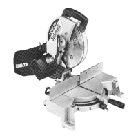
2. Fig. 5, illustrates the lockpin (A) pulled out and the
cuttinghead (B) in the up position.
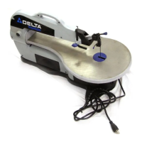
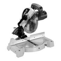
MOVING TABLE TO
THE 90 DEGREE
C U T-OFF POSITION
1. Depress t able lock lever (A) Fig. 6, and rot ate t able (B)
to the 90 degree straight cut-of f position. Then release
lock lever (A).
B
A
B
A
B
A
 Loading...