14
Fig. 20
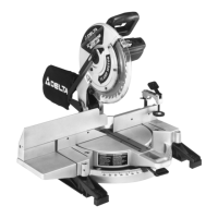
ADJUSTING SLIDING FIT
BETWEEN MOVABLE
TABLE AND BASE
If it ever becomes necessary to adjust the sliding fit
between the movable t able and the base, turn nut (A)
Fig. 20, clockwise to increase or counterclockwise to
decrease the sliding fit. This adjustment should not be
too tight that it restrict s the rot ating movement of the
table or too loose that it af fect s the accuracy of the saw.
Fig. 21
Fig. 22
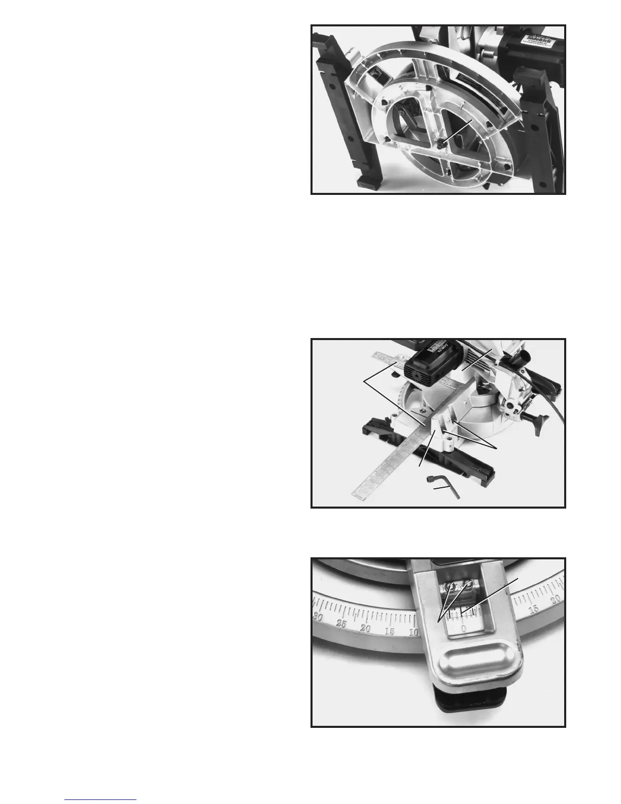
ADJUSTING FENCE 90 DEGREES TO BLADE
IMPORTANT:BEFORE MAKING THIS ADJUSTMENT MAKECERTAIN THE BLADE IS SET
AT 90 DEGREES TO THE TABLE. SEE SECTION ADJUSTING 90 A N D 45 DEGREE BEVEL
POSITIVE S TOPS.
1. DISCONNECT THE S AW FROM THE POWER
SOURCE.
2. Rot ate the movable t able so that the blade is 90
degrees to the fence and the spring-loaded positive stop
for the 0 degree mark on the scale is engaged.
3. Using a square (A) Fig. 21, place one end of the
square against the front of the fence (B) and the other
end against the blade (C), with the blade in the down
position, as shown. Check to see if the fence is 90
degrees to the blade.
4. If an adjustment is necessary, the fence (B) Fig. 21,
can be adjusted by loosening the four screws, two of
which are shown at (D), that att ach the fence to the base,
using wrench (E) supplied. Adjust the fence (B) as
required and tighten the four screws (D).
5.Af ter you are sure the fence is 90 degrees to the
blade, adjust the cursor (F) Fig. 22, so the pointer is
aligned with the 0 degree mark on the scale by loosen -
ing two screws (G), adjusting cursor (F) and tightening
screws (G).
A
A
B
E
D
C
G
F
 Loading...