13
3. The compound miter saw is equipped with spring-loaded positive stops at the 90 degree straight cut-of f
position and at the 15, 22.5, 31.62 and 45 degrees right and lef t miter positions. These spring-loaded
positive stop s can be felt as you are rot ating the t able. NOTE: The 31.62 degree right and lef t miter positive
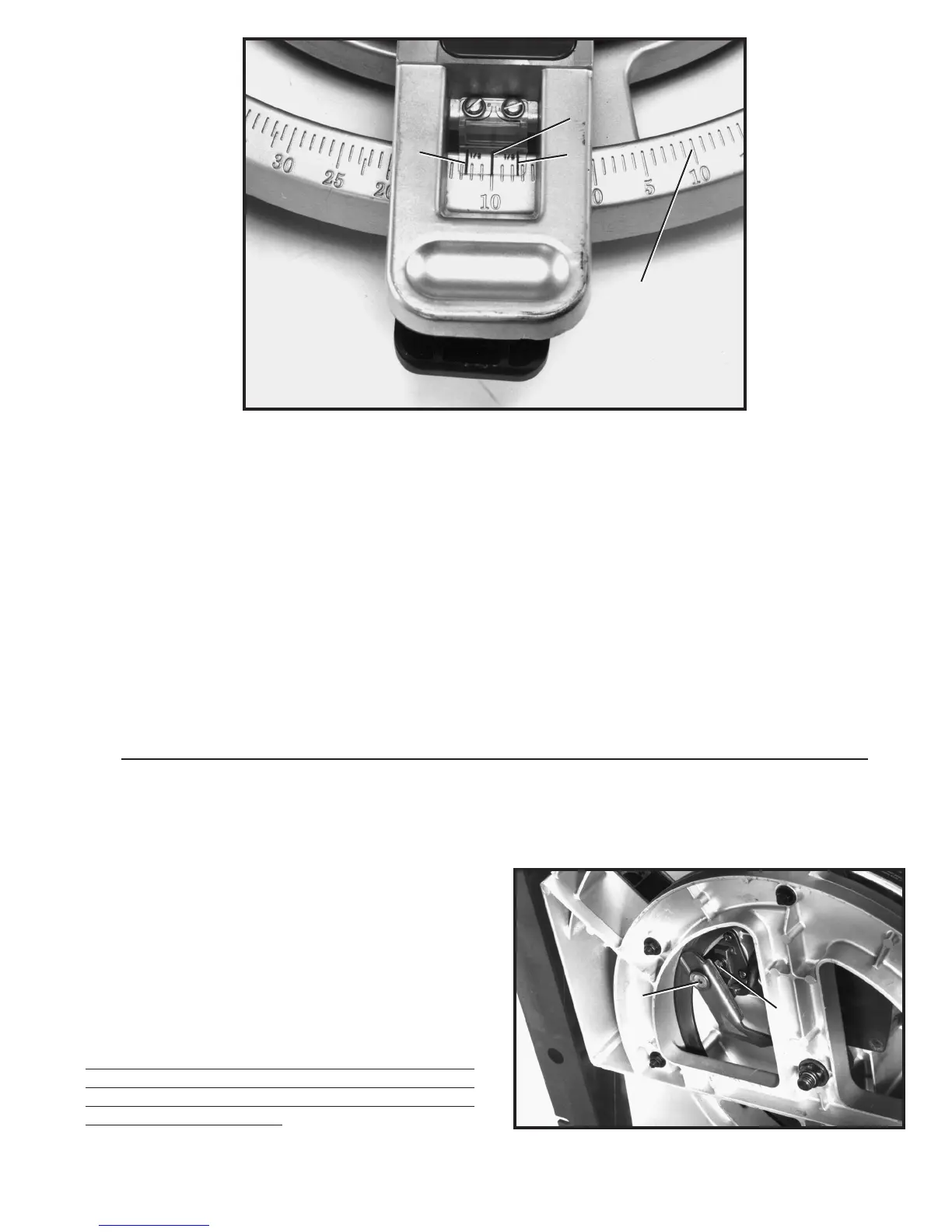
stop s are used when cutting crown moulding as explained later in this manual. A large scale (B) Fig. 18, and
cursor (C) is provided for intermediate angles.
4. The center line (C) Fig. 18, on the cursor indicates the actual angle of cut. Each line on the scale (B)
represent s one degree. In ef fect, when the center line (C) is moved from one line to the next on the scale,
the angle of cut is changed by one degree.
5. The pointer is provided with two additional lines (D) and (E) Fig. 18. This allows you to move the control
arm exactly 1/2 degree. For example, assume the center line (C) is pointing to the 10 degree mark on the
scale, as shown, and you want to change the angle of cut 1/2 degree to the right. Move the control arm until
the right line (E) lines up with the next line on the scale. The angle of cut will then be changed 1/2 degree to
the right. If you were changing the angle of cut 1/2 degree to the lef t, use the lef t line (D) in the same mann er.
Fig. 19
When rotating the t able, the t able locking lever must be
depressed. When the locking lever is not depressed, the
table should be in the locked position. If af ter a long period
of time the clamping action of the t able locking mechan-
ism needs adjusted, proceed as follows:
1. Loosen locknut (A) Fig. 19, using open end wrench
supplied. T urn screw (B) with allen wrench supplied. T urn
screw clockwise to increase or counterclockwise to de-
crease clamping action of locking lever. IMPORTANT:
Af ter adjustment is completed tighten locknut (A),
just enough to t ake all play out of the handle assembly.
Tightening locknut (A) too much will defeat the
purpose of the adjustment.
ADJUSTING CLAMPING ACTION OF
TABLE LOCKING MECHANISM
Fig. 18
D
E
C
B
B
A
 Loading...