7
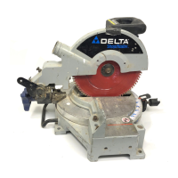
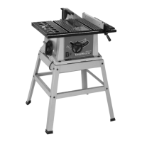
Fig. 7
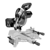
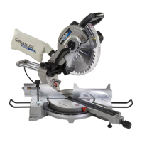
Fig. 7A
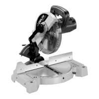
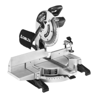
Fig. 7B
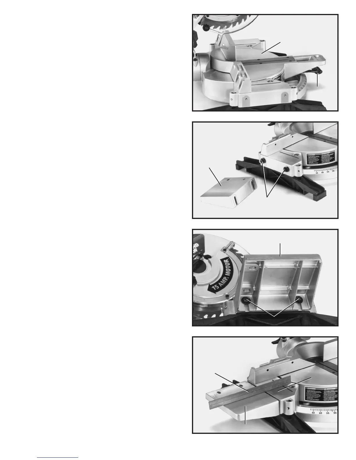
Fig. 7C
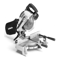
2. Fig. 7, illustrates the t able (B) in the 90 degree
straight cut-of f position. NOTE: Table lock lever (A) must
be depressed when rotating t able. When lock lever (A) is
not depressed, the t able is in the locked position and
cannot be moved.
3. For proper operation and adjustment of the t able, refer
to sections, R O T A TING TABLE FOR MITER CUTTING,
ADJUSTING CLAMPING ACTION O F TABLE LOCKING
MECHANISM and ADJUSTING SLIDING FIT BETWEEN
M O VABLE TABLE AND BASE.
ASSEMBLING EXTENSION
TABLE AND FENCE SLIDE
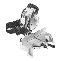
1. Place 5/16 lockwasher and 5/16 flat washer on
each 1/2 long hex head screw (A) Fig. 7A, and thread
the two screws (A) into the two threaded holes on lef t
side of saw t able, as shown. NOTE: Only thread the
screws a few threads into the holes at this time.
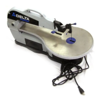
2. Assemble the table extension (B) Figs. 7A and 7B, to
lef t side of saw t able making sure groove of t able exten -
sion (B) is inside flat washers as shown in Fig. 7B.
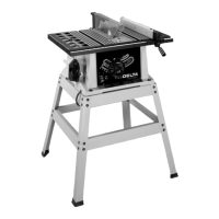
3. Using a straight edge (C) Fig. 7C, make cert ain
extension t able (B) is level with saw t able (D) as shown,
and tighten the two screws (A) Fig. 7B.
B
A
B
A
B
A
B
C
D
 Loading...