Chapter 4 Description of Parameters | VFD-VJ
4-30
Set Bit2 = 0
Multi-function input
terminal = 47
Multi-function input
terminal = 48
OFF OFF PI1 (Pr.00-20 and Pr.00-21) and Pr.00-10: Speed
Bandwidth
ON OFF PI2 (Pr.00-22 and Pr.00-23) and Pr.00-50: Speed
Bandwidth 2
OFF ON PI3 (Pr.00-24 and Pr.00-25) and Pr.00-51: Speed
Bandwidth
Set Bit2 =1
Multi-function input
terminal = 47
Multi-function input
terminal = 47
OFF OFF PID1 (Pr.00-20, Pr.00-21 and Pr.00-37) and Pr.00-10:
Speed Bandwidth
ON OFF PID2 (Pr.0-22, Pr.02-23 and Pr.00-40) and Pr.00-50
Speed Bandwidth 2
OFF ON PID3 (Pr.00-24, Pr.00-25 and Pr.00-41) and Pr.00-51:
Speed Bandwidth 3
When the Bit 1 of this parameter is set as 1, the pressure feedback is lower than the pressure stable region
(please refer to the description of Pr.00-26) so the flow control will be performed.
When it enters the
pressure stable region, the pressure control will be applied.
When Bit1= 0, the Pressure Response is slow and the pressure overshoot is weak.
When Bit1 = 1, the Pressure Response is fast and the pressure overshoot is strong.
Set Bit2 = 0, the setting at Pr.00-39 and Pr.00-42 are used to suppress pressure overshoot.
But when Bit2 = 1, the setting at Pr.00-37 is used to suppress pressure overshoot.
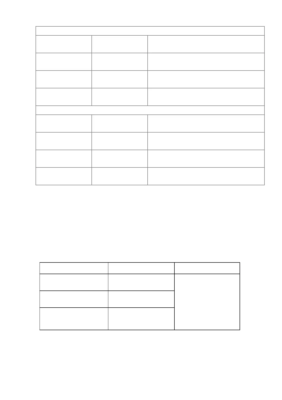
When Bit3 =1:
Pressure
Command
P, I Gain and Speed
Bandwidth
D
(Set Bit2 =1)
Smaller than or equal to the
maximum pressure command
(Pr.00-07)*25%
PI1 (Pr.00-20 and Pr.00-21)
and Pr.00-10: Speed
Bandwidth
Pr.00-37
Equal to the maximum value
for pressure command
(Pr.00-07)
PI2 (Pr.00-22 and Pr.00-23)
and Pr.00-50: Speed
Bandwidth 2
Pressure command between
25% and 100%.
The PI Gain and Speed
Bandwidth can be obtained by
calculating the linear
interpolation.
 Loading...
