Chapter 12 Description of Parameter SettingsMS300 (High Speed Model)
12-02-8
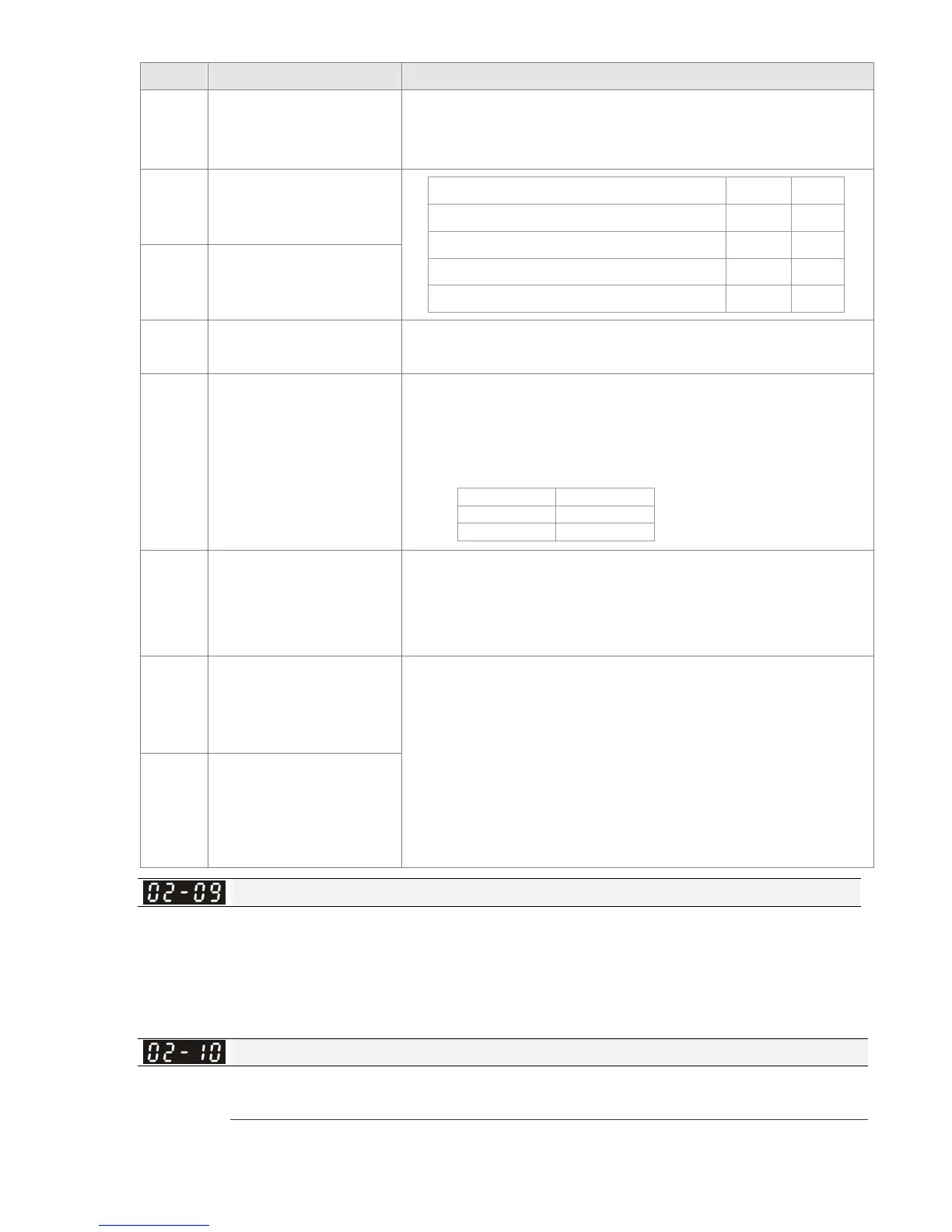
Settings Functions Descriptions
50 Master dEb input
Input the message setting in this parameter when dEb occurs to
Master. This will ensure that dEb also occurs to Slave, then
Master and Slave will stop simultaneously.
51
Selection for PLC mode
(bit 0)
PLC status bit 1 bit 0
Disable PLC function (PLC 0) 0 0
Trigger PLC to operate (PLC 1) 0 1
Trigger PLC to stop (PLC 2) 1
No function 1 1
52
Selection for PLC mode
(bit 1)
53
Trigger CANopen quick
stop
When this function is enabled under CANopen control, it will
change to quick stop. Refer to Chapter 15 for more details.
56
LOCAL / REMOTE
selection
Use Pr. 00-29 to select LOCAL / REMOTE mode (refer to Pr.
00-29).
When Pr. 00-29 is not set to 0, the digital keypad KPC-CC01
(optional) will display the status of LOC / REM.
bit 0
REM 0
LOC 1
81
Zero point position signal
input of simple
positioning
Use this function as trigger terminal for simple positioning with
Pr. 01.20~01.25. This function is for simple positioning,
positioning accuracy should be evaluated by the user. Refer to
Pr. 01-25 for more details.
83
Multi-motors (IM)
selection bit 0
When the contact of this function is ON, parameters can be
changed (Pr. 01.01~01.06, Pr. 01.26~01.43, Pr. 07.18~07.38,
Pr. 07.00~07.06)
Example: MI1 = 27, MI2 = 28
When MI1 OFF, MI2 OFF: motor 1
MI1 ON, MI2 OFF: motor 2
MI1 OFF, MI2 ON: motor 3
MI1 ON, MI1 ON: motor 4
84
Multi-motors (IM)
selection bit 1
UP / DOWN Key Mode
Factory Setting: 0
Settings 0: UP / DOWN by the accel. / decel. time
1: UP / DOWN constant speed (Pr. 02-10)
2: Pulse signal (Pr. 02-10)
3: External terminals UP / DOWN key mode
Constant Speed. the Accel. / Decel. Speed of the UP / DOWN Key
Factory Setting: 0.001
Settings 0.001~1.000 Hz / ms
These settings are used when multi-function input terminals are set to 19, 20 (UP / DOWN
Command). The frequency increases / decreases according to Pr. 02-09 and Pr. 02-10.
 Loading...


