Chapter 12 Description of Parameter SettingsMS300 (High Speed Model)
12-02-10
bit 0 ~ bit 6 correspond to MI1 ~ MI7 respectively.
bit 0 (MI1) default is FWD terminal, bit 1 (MI2) default is REV terminal. This parameter cannot be
used to change input mode when Pr. 02-00 ≠ 0.
User can change terminal ON / OFF status by communicating.
For example: MI3 is set to 1 (multi-stage speed command 1), MI4 is set to 2 (multi-stage speed
command 2). Then the forward + 2
nd
stage speed command = 1001
2
= 9
10
As long as Pr. 02-12 = 9 be set by communication, there is no need to make wiring of any
multi-function terminal to run forward with 2
nd
stage speed.
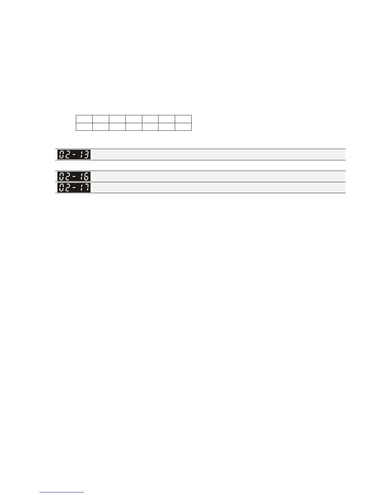
bit 6 bit 5 bit 4 bit 3 bit 2 bit 1 bit 0
MI7 MI6 MI5 MI4 MI3 MI2 MI1
Use Pr. 11-42 bit 1 to select whether FWD / REV terminal is controlled by Pr. 02-12 bit 0 and bit 1.
Multi-function Output 1 (Relay1)
Factory Setting: 11
Multi-function Output 2 (MO1)
Multi-function Output 3 (MO2)
Factory Setting: 0
Settings 0: No function
1: Operation indication
2: Operation speed attained
3: Desired frequency attained 1 (Pr. 02-22)
4: Desired frequency attained 2 (Pr. 02-24)
5: Zero speed (Frequency command)
6: Zero speed, include STOP (Frequency command)
7: Over torque 1 (Pr. 06-06~06-08)
8: Over torque 2 (Pr. 06-09~06-11)
9: Drive is ready
10: Low voltage warning (LV) (Pr. 06-00)
11: Malfunction indication
13: Overheat warning (Pr. 06-15, OH1)
14: Software brake signal indication (Pr. 07-00)
17: Count value attained (Pr. 02-20; not return to 0)
18: Count value attained (Pr. 02-19; returns to 0)
19: External interrupt B.B. input (Base Block)
20: Warning output
21: Over voltage warning
22: Over-current stall prevention warning
23: Over-voltage stall prevention warning
24: Operation source
25: Forward command
26: Reverse command
29: Output when frequency
≧ Pr.02-34 (≧ 02-34)
 Loading...


