Chapter 12 Description of Parameter SettingsMS300 (High Speed Model)
12-02-15
Multi-function Output Direction
Factory Setting: 0000
Settings 0000h~FFFFh (0:N.O.; 1:N.C.)
The setting of this parameter is in hexadecimal.
This parameter is set via bit setting. If the bit is 1, the corresponding multi-function output acts in
the opposite way.
Example:
If Pr. 02-13 = 1 (Indicate when operating). If output is positive, bit is set to 0, then Relay 1 is ON
when the drive runs and is OFF when the drive stops. On the contrary, if action is reversed, bit is
set to 1, then Relay is OFF when the drive runs and is ON when the drive stops.
bit 4 bit 3 bit 2 bit 1 bit 0
MO2 MO1 reserved reserved RY
Terminal Counting Value Attained (return to 0)
Factory Setting: 0
Settings 0~65500
This parameter needs to use KPC-CC01 (optional).
Input point of the counter can be set by multi-function terminal MI6 as a trigger terminal (set
Pr. 02-06 to 23). When counting completed, the specified multi-function output terminal will be
activated (Pr. 02-13, Pr. 02-36, Pr. 02-37 is set to 18). Pr. 02-19 cannot be set to 0 at this time.
When displayed c5555, the drive has counted 5,555 times. If displayed c5555
, the actual count
value is 55,550 ~ 55,559.
Preliminary Counting Value Attained (not return to 0)
Factory Setting: 0
Settings 0~65500
This parameter needs to use KPC-CC01 (optional).
When the count value counts from 1 to attain this value, the corresponding multi-function output
terminal will be activated (Pr. 02-13, Pr. 02-36, Pr. 02-37 is set to 17). This parameter can be used
for the end of counting to make the drive runs from the low speed to stop.
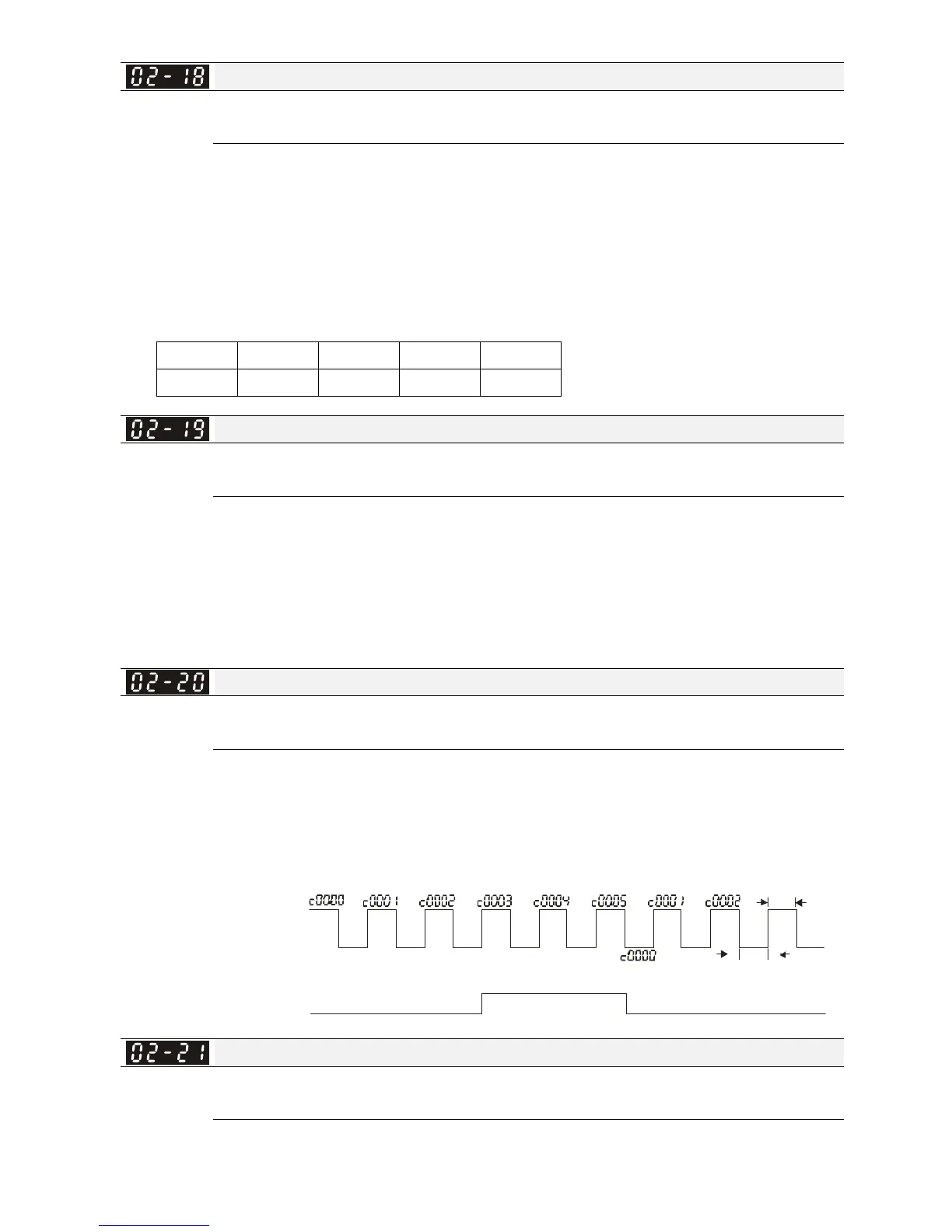
Time series diagram is shown below:
1.0 msec
TRG
[00-04=01]
02-20=3
[02-06=23]
Displayed value
External counter trigger signal
(Output signal)
Multi-function output terminal
Attain count assigned
RY1 Pr.02-13=17
The width of trigger signal
02-13, 02-14, 02-36, 02-37
1.0 msec
Digital Output Gain (DFM)
Factory Setting: 1
Settings 1~22
It is used to set the signal for the digital output terminals (DFM-DCM) and digital frequency output
(pulse, work period = 50 %). Output pulse per second = output frequency X Pr. 02-21.
 Loading...


