Chapter 15 CANopen OverviewMS300 (High Speed Model)
15-17
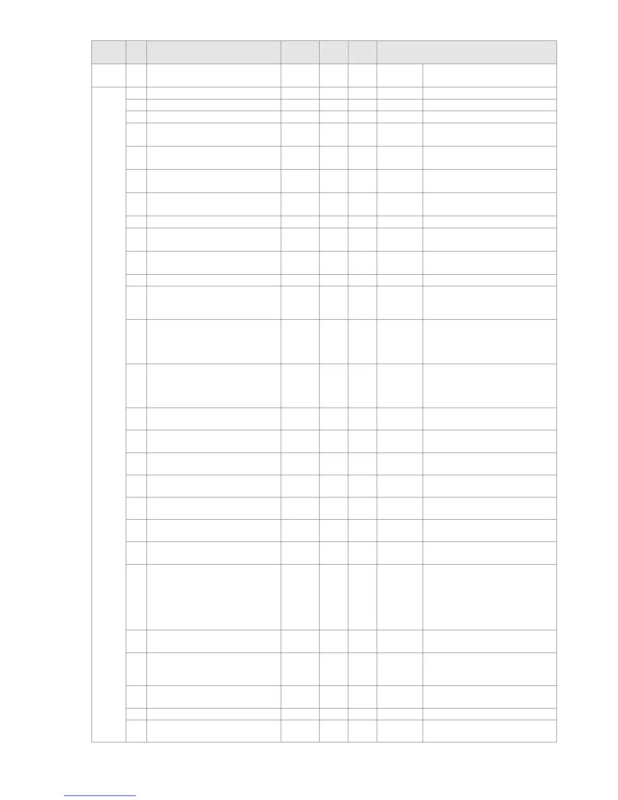
Index Sub Definition
Factory
Setting
R/W Size Note
17
Multi-function display
(Pr. 00-04)
0 R U16
2022H
0 Reserved 0 R U16
1 Display output current 0 R U16
2 Display counter value 0 R U16
3
Display actual output
frequency (XXX.XX Hz)
0 R U16
4
Display DC-BUS voltage
(XXX.X V)
0 R U16
5
Display output voltage
(XXX.X V)
0 R U16
6
Display output power angle
(XX.X °)
0 R U16
7 Display output power in kW 0 R U16
8
Display actual motor speed
(rpm)
0 R U16
9
Display estimate output
torque (XXX.X %)
0 R U16
A Display PG feedback 0 R U16
B
Display PID feedback value
after enabling PID function in
% (To 2 decimal places)
0 R U16
C
Display signal of AVI analog
input terminal, 0-10V
corresponds to 0-100 % (To 2
decimal places)
0 R U16
D
Display signal of ACI analog
input terminal, 4-V 20 mA /
0-10 V corresponds to 0-100
% (To 2 decimal places)
0 R U16
F
Display the IGBT temperature
of drive power module in
o
C
0 R U16
10
Display the temperature of
capacitance in
o
C
0 R U16
11
The status of digital input (ON
/ OFF), refer to Pr. 02-12
0 R U16
12
The status of digital output
(ON / OFF), refer to Pr. 02-18
0 R U16
13
Display the multi-step speed
that is executing
0 R U16
14
The corresponding CPU pin
status of digital input
0 R U16
15
The corresponding CPU pin
status of digital output
0 R U16
16
Number of actual motor
revolution (PG1 of PG card).
It will start from 9 when the
actual operation direction is
changed or keypad display at
stop is 0. Max. is 65535
0 R U16
17
Pulse input frequency (PG2
of PG card)
0 R U16
18
Pulse input position (PG card
PG2), maximum setting is
65535.
0 R U16
1A
Display times of counter
overload (0.00~100.00 %)
0 R U16
1B Display GFF in %
0 R U16
1C
Display DC-BUS voltage
ripples (Unit: VDC)
0 R U16
 Loading...


