3
1
2
4
5
6
7
5
b1
b2
6
7
4
9
1
8
b1
2
42583844.eps
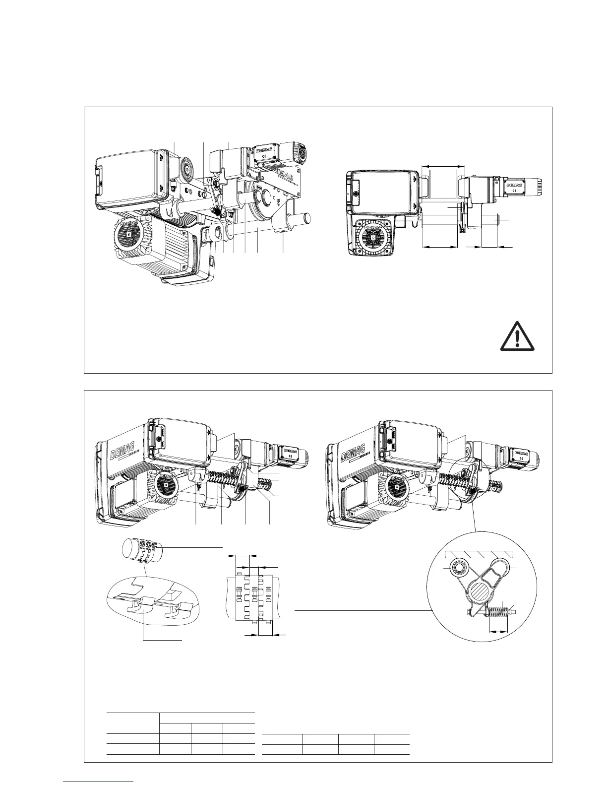
Place the travel rollers of wheel legs (4) – drum side – onto the girder flange and slide wheel legs (1) on the opposite
side – travel motor side – towards the girder.
Reference dimension between both opposite guide rollers is flange width b +1 mm.
After adjusting the travel unit, press supporting roller (6) against the bottom flange of the girder by means of tensioning
screw (7). Tension supporting roller (6) until the travel wheel is in contact with the girder flange.
Assembly of the travel unit on the track girder
Assembly of the spacer sleeves
(only on the crossbar side with supporting roller)
1. Measure distance x1 between wheel legs (4) and supporting roller (6).
2. Measure distance x2 between wheel legs (1) and retaining ring with washer (8).
3. This is done to determine the number of spacer sleeves (9).
Spacer sleeve (9) is now opened and fitted on connecting rods (2).
Spacer sleeve dimensions (9)
egnaR
mmnihtdiW
1b2b2b+1b
5RD/3RD9,222,511,83
01RD3,228,411,73
Determine dimension L of pre-tensioned pressure spring (10).
To obtain the pressure force of supporting rollers (6), shorten
length L of pressure spring (10) by “dimension x”.
egnaR3RD5RD01RD
]mm[x-.miD2,6-2,5-5,7-
42583744.eps
Final adjustment of the supporting rollers
L
6
6
7
10
Fit the clamps for fastening
the cable in one row.
Locking hook
Pre-tensioning of pressure spring (10)
After having adjusted the travel unit, press support-
ing roller (6) against the bottom flange of the girder
by means of tensioning screw (7). Tension support-
ing roller (6) until the travel wheel is in contact with
the girder flange.
42584044.eps
42583944.eps
Fix side cheek (1) on connecting rod (2+3)
with threaded pins (5).
DR 3 range = 150 Nm
DR 5/10 range = 200 Nm
Minimum flange thickness
DR 3 min. 10 mm
DR 5 min. 12 mm
DR 10 min. 15 mm
 Loading...