21491244.p65/201204
30
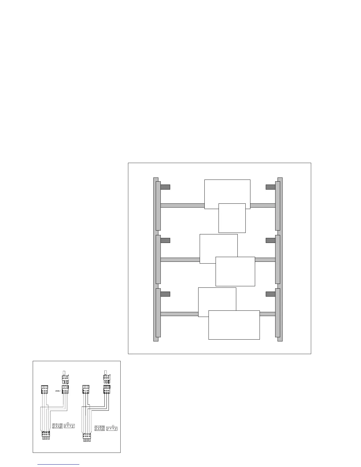
The crane set can be ordered with an anti-collision device for a crane located in the
centre or on the side.
For this purpose, the type of switch-off (fast, general, 2-stage or without), the
position of the crane, the position of the main conductor line (side 1 or 2, see
sketch below) and whether the light barrier is to be self-monitoring or not must be
selected.
E.g.
• Crane1
• Main conductor line side 2
• 2-stage limit switch FORWARD
• Optical backward general
• Without self-monitoring
Special designs (turning of a crane, changing the side for operating the con-
trol pendant etc.) must be considered separately.
The following Y connectors are required for connecting the limit switches and/or
light barriers in the crane bridge enclosure:
• Y Connector X16 Part no. 719 863 45
• Y Connector X48 Part no. 719 864 45
8 Crane anti-collision device
42678944.eps
3
X48
3
1
2
2
1
3
4
4
4
3
1
2
1
1X48.1
3
2
1
431
2
1
3
1
2
1
2
3
3
2
4
31
2
1)
X16
2
1
3
4
12
34
1
3
4
4
21
2)
1X16.1
2
1
3
1
2X16.1
3 4
2
1
3
1
2
1
2
3
3
2
1
3
4
2
42679644.eps
End of building I
Limit switch FORWARD
Fast
General
2-stage
without
Optical
BACKWARD
Fast
General
2-stage
Optical FORWARD
Fast
General
2-stage
without
Optical BACKWARD
Fast
General
2-stage
without
Optical FORWARD
Fast
General
2-stage
Limit switch BACKWARD
Fast
General
2-stage
without
Crane 1
Crane
side 2
Centre crane
Left
Crane 2
Right
Crane
side 1
End of building II
 Loading...