29
21491244.p65/201204
7.4 Electrical design and
connector insert
7.4.1 ZBF two-speed motor with
brake
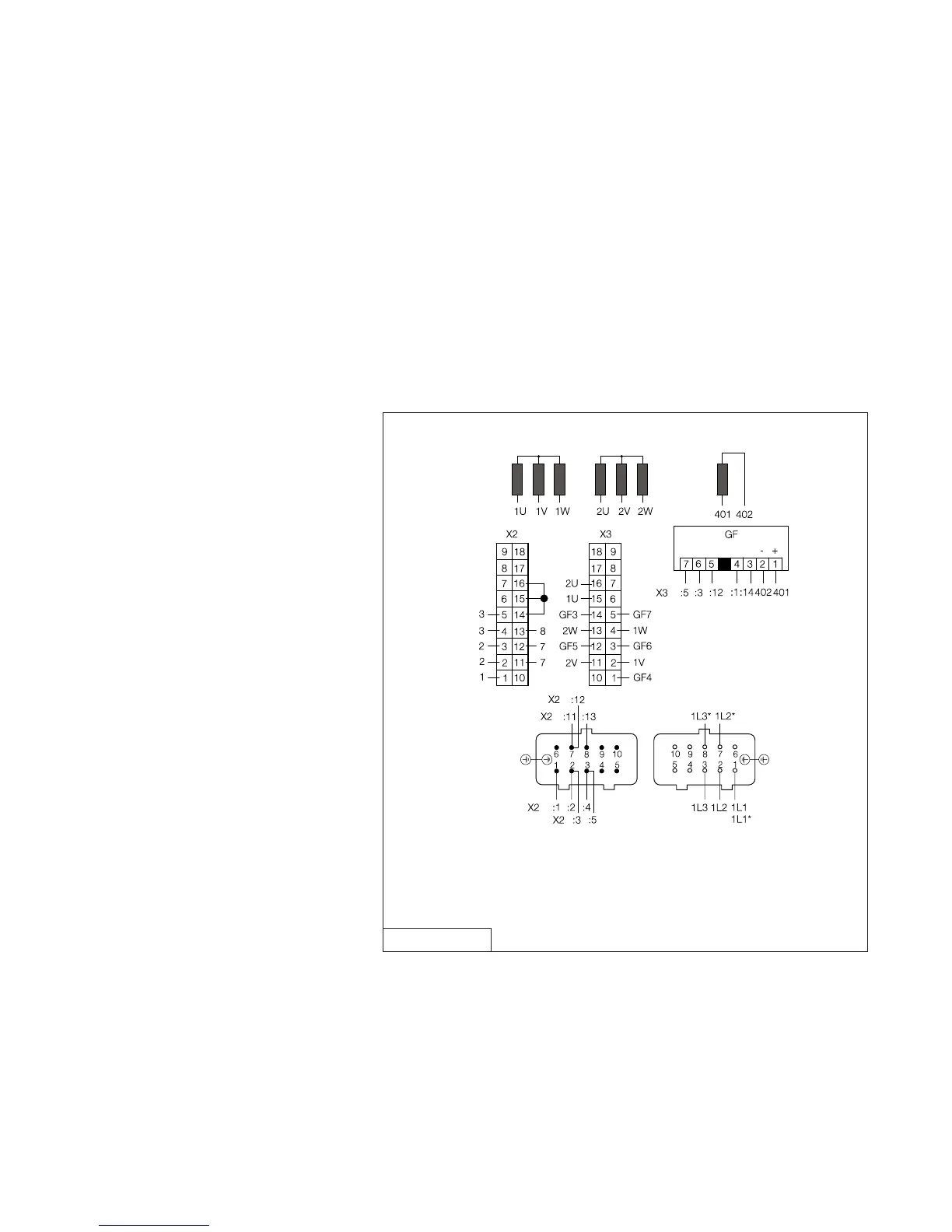
The motor has two separate windings and can be operated with two speeds.
The GF combined brake module is used.
Circuit diagram 038 682 84 shows the connection of a Z-type motor with two
speeds and brake. The DC brake is connected to the power supply of the motor via
the GF module.
Additionally the GF module measures the motor current and switches the brake on
the DC side.
Power is supplied to the motor and to the brake with the phases 1L1, 1L2 and 1L3
via connections 1, 7 and 8 for high speed and via connections 1, 2 and 3 on the
connector for low speed.
038 682 84
Motor side
Line side
The module combines three functions in one unit. The module is used parallel to the
motor winding. It is used for normal excitation of the DC brake. Additionally motor-
current dependent brake switch-off in the DC circuit is integrated in the GF module.
The GF module also features an integral varistor set that protects the high-pole
winding.
The GF combined module is used for pole-changing travel motors, sizes 63 - 100.
7.4.2 GF combined brake module
Connectors
Motor
High speed
Low
speed
2 windings, 2 speeds, 1 voltage Y/Y
Common power supply of motor and GF brake control module
 Loading...