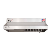
D1000 Installation and Service Manual 9
Home LAB-110073 Rev. 3
1. 120 VAC Input (not provided)
a. 120 VAC 15 Amp circuit provided by installer
b. Voltage supply from the Main Breaker Panel to the 5-15R Receptacle (not provided)
2. 120 VAC 15 Amp Plug Input to Hood (provided)
a. 12 Ft in length
b. Power Cord from the Hood and connects to the 5-15R Receptacle (not provided)
3. 120 VAC Output from Hood (provided)
a. 8 Ft in length
b. One 14/2 MC Wire
c. Cable from the Hood to the Clock Box (if applicable) or the Power Source Disconnect for the Range
(Gas or Electric)
4. 120 VAC Input (not provided)
a. 120 VAC 15 Amp circuit provided by installer
b. Voltage supply from the Main Breaker Panel to Clock Box (not provided)
5. 120 VAC Input to Power Source Disconnect for the Range (not provided)
a. 120 VAC Provided by installer
6. 5 VDC Input / Output Communication cable encased in 16 mm ENT Flexible Conduit (provided)
a. 25 Ft in length
b. One communication cable
c. Connects to the Clock Box PLC and HMI / Touch Screen
7. Power Source Disconnect (not provided)
a. 120 VAC jumper between Electric and Gas Disconnects