IN
S-VIDEO
OUT
S-VIDEO
OUT
S-VIDEO
OUT IN
S-VIDEO
VIDEO IN
VIDEO OUT
VIDEO IN
VIDEO OUT
VIDEO OUT
B
B
DVD player, VDP, etc.
Monitor TV
TV or
satellite broadcast tuner
Connecting a DVD player or
video disc player (VDP)
Connecting a monitor TV
Connecting the video deck
Connecting a TV/DBS tuner
DVD/VDP
• Connect the DVD player’s or video disc player’s
S-Video output jack to the S-VIDEO DVD/VDP IN
jack using an S-Video connection cord.
MONITOR OUT
• Connect the TV’s or DBS tuner’s S
video input (S-VIDEO INPUT) to the
MONITOR OUT jack using a S
jack connection cord.
S-VIDEO
• Connect the TV’s or DBS tuner’s S video output jack
(S-VIDEO OUTPUT) to the TV/DBS IN jack
using an S jack connection cord.
S-VIDEO
• Connect the video deck’s S output jack (S-OUT) to the
VCR IN jack and the video deck’s S input jack (S-
IN) to the VCR OUT jack using S jack connection
cords.
S-VIDEO
S-VIDEO
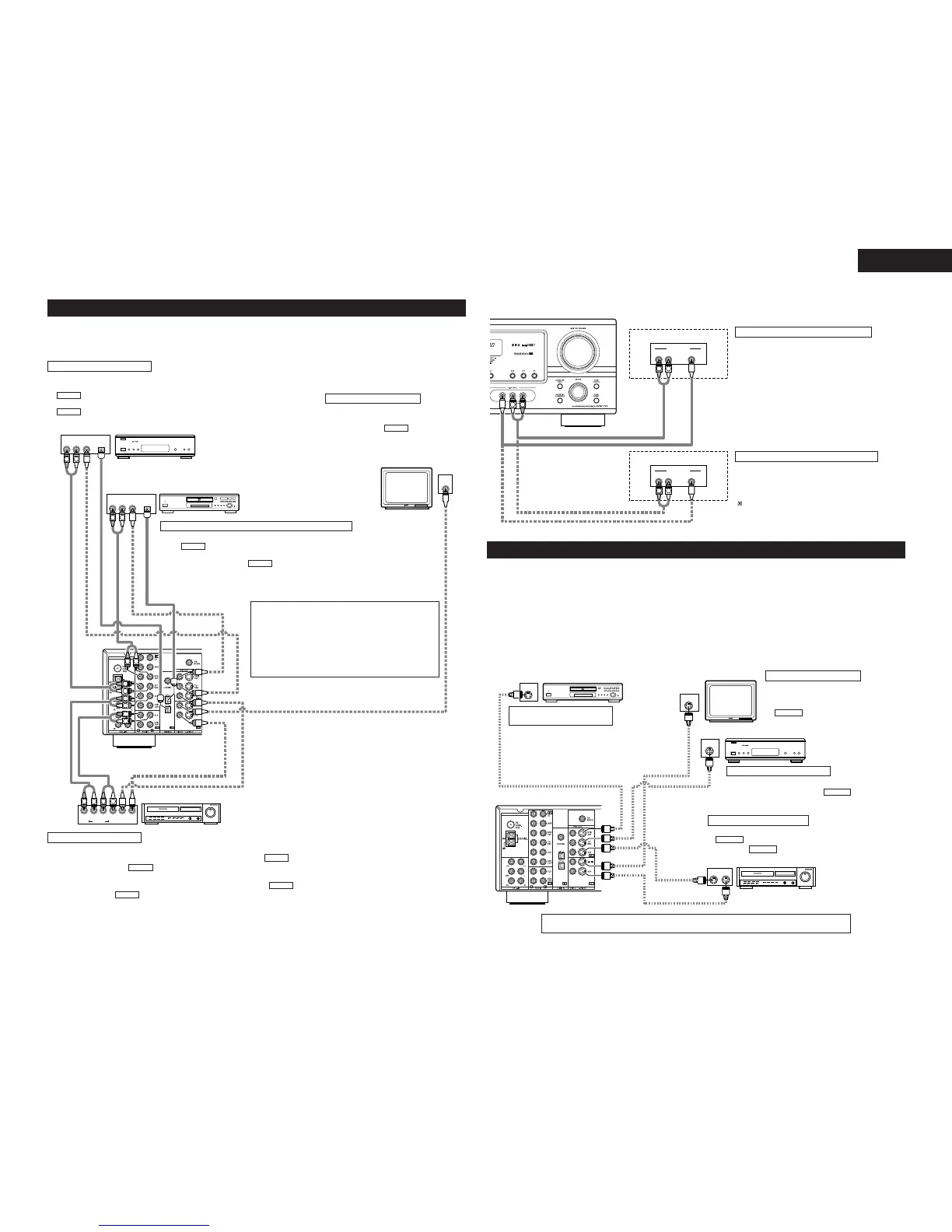
Connecting a video component equipped with S-video jacks
• When marking connections, also refer to the operating instructions of the other components.
• A note on the S input jacks
The input selectors for the S inputs and pin jack inputs work in conjunction with each other.
• Precaution when using S-jacks
This unit’s S-jacks (input and output) and video pin jacks (input and output) have independent circuit structures,
so that video signals input from the S-jacks are only output from the S-jack outputs and video signals input
from the pin jacks are only output from the pin jack outputs.
When connecting this unit with equipment that is equipped with S-jacks, keep the above point in mind and
make connections according to the equipment’s instruction manuals.
Connecting the video equipments
To connect the video signal, connect using a 75 Ω/ohms video signal cable cord. Using an improper cable can
result in a drop in sound quality.
R OUT
VIDEO
OPTICAL
OUT
L
AUDIO
OUT
DIGITAL
IN
VIDEO
R
L
R
L
R
L
L
R
R OUT IN
AUDIO
VIDEO
OUT IN
LRL
R
L
R
L
L
R
R OUT
VIDEO
OPTICAL
OUT
L
AUDIO
OUT
DIGITAL
L
R
B
B
AUDIO OUT
VIDEO OUT
AUDIO OUT
VIDEO OUT
AUDIO OUT
AUDIO IN
VIDEO IN
VIDEO OUT
DVD player or VDP
Monitor TV
Connecting a TV/DBS tuner
TV/DBS
• Connect the TV’s or DBS tuner’s video output jack (VIDEO OUTPUT) to the
(yellow) TV/DBS IN jack using a 75 Ω/ohms video coaxial pin plug cord.
• Connect the TV’s or DBS tuner’s audio output jacks (AUDIO OUTPUT) to the
TV/DBS IN jacks using pin plug cords.
AUDIO
VIDEO
Connecting a DVD player or a video disc player (VDP)
MONITOR OUT
• Connect the TV’s video input jack (VIDEO
INPUT) to the MONITOR OUT
jack using a 75 Ω/ohms video coaxial pin
plug cord.
VIDEO
NOTE:
Connection of the video disc Player Equipped with
Dolby Digital RF Output Jack.
• Please use a commercially available adaptor when
connecting the Dolby Digital RF output jack of the
video disc player to the digital input jack.
Please refer to the instruction manual of the adapter
when making connections.
Video input/output connections:
• Connect the video deck’s video output jack (VIDEO OUT) to the (yellow) VCR IN jack, and the video deck’s video input
jack (VIDEO IN) to the (yellow) VCR OUT jack using 75 Ω/ohms video coaxial pin plug cords.
Connecting the audio output jacks:
• Connect the video deck’s audio output jacks (AUDIO OUT) to the VCR IN jacks, and the video deck’s audio input jacks
(AUDIO IN) to the VCR OUT jacks using pin plug cords.
AUDIO
AUDIO
VIDEO
VIDEO
Connecting a video deck
• Connect the DVD player’s (video disc player’s) video output jack (VIDEO OUTPUT) to
the (yellow) DVD/VDP IN jack using a 75 Ω/ohms video coaxial pin plug cord.
• Connect the DVD player’s (video disc player’s) analog audio output jacks (ANALOG
AUDIO OUTPUT) to the DVD/VDP IN jacks using pin plug cords.
• For better sound quality, we recommend using the DVD player with digital rather than
analog connections.
DVD and VDP players can also be connected to the VCR terminals.
AUDIO
VIDEO
Connecting a monitor TV
Video deck
Video deck
Connect the components’ audio inputs and outputs as described on page 7.
TV or DBS tuner
R VIDEO OUTL
OUTPUT
R VIDEO OUTL
OUTPUT
LINE OUT
VIDEO OUT
VIDEO OUT
LINE OUT
L
R
L
R
L
R
Video game
Connecting a Video game equipment
• Connect the Video game equipment’s output jacks
to this unit’s V. AUX INPUT jacks.
Video camera
Connecting a Video camera equipment
• Connect the video camera equipment’s output
jacks to this unit’s V. AUX INPUT jacks.
The V. AUX terminal is covered with a cap.
Remove this cap in order to use the terminal. (See
page 3 for instructions on removing the cap.)
 Loading...