7
AVR-3310CI/AVR-3310/AVR990/AVC-3310
About the photos used for descriptions in the “DISASSEMBLY” section.
• The direction from which the photographs used herein were photographed is indicated at "Direction of photograph: ***" at
the left of the respective photographs.
• Refer to the table below for a description of the direction in which the photos were taken.
• Photographs for which no direction is indicated were taken from above the product.
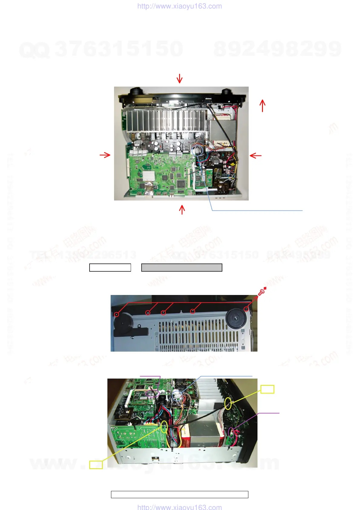
1. FRONT PANEL UNIT ASSY
(1) Remove the screws.
(2) Cut the wire clampers then disconnect the connector wires.
Front side
Direction of photograph: B
Direction of photograph: D
Direction of photograph: C
Direction of photograph: A
The viewpoint of each photograph
(Photografy direction)
[View from above]
Except AVR-3310CI, AVR-990 model
s
d
Proceeding : TOP COVER →
FRONT PANEL UNIT ASSY
View from bottom
d
Except EUEC model
cut
cut
CX021
CY052
Direction of photograph: D
s
w
w
w
.
x
i
a
o
y
u
1
6
3
.
c
o
m
Q
Q
3
7
6
3
1
5
1
5
0
9
9
2
8
9
4
2
9
8
T
E
L
1
3
9
4
2
2
9
6
5
1
3
9
9
2
8
9
4
2
9
8
0
5
1
5
1
3
6
7
3
Q
Q
TEL 13942296513 QQ 376315150 892498299
TEL 13942296513 QQ 376315150 892498299
http://www.xiaoyu163.com
http://www.xiaoyu163.com
 Loading...