20
AVR-4802/AVC-A11SR
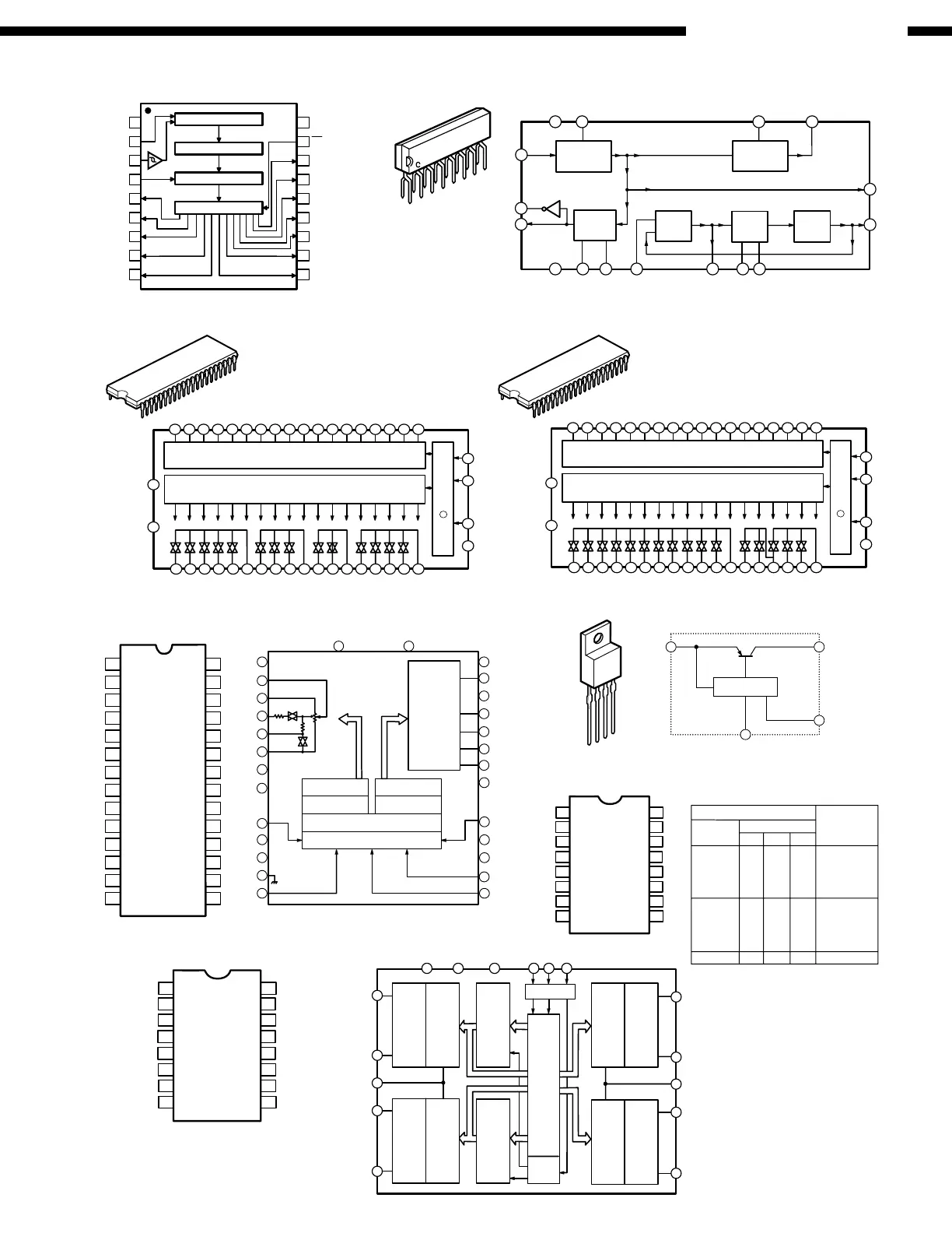
NJM2229S (IC417)
1
16
Sync Sepa
Sync Det
Phase
Det
Vsync Sepa
32fH
VCO
1/32
15
7
9
10
5
16
1
23
4
1211
8
13
14
6
C9184AP (IC401, 403)
2
3
4
5
6
1
16
7
8
9
10
15
14
13
12
11
BASS+
BASS
−
COM
TREBLE
−
TREBLE+
Vss
V
DD
GND
CK
DATA
STB
BASS+
BASS
−
COM
TREBLE
−
TREBLE+
Ladder resister
Analog switch
13 bit latch circuit
Level shift
20 bit Shift register circuit
Analog switch
Ladder resister
Ladder resister
Analog switch
13 bit latch circuit
Code
detect
circuit
Analog switch
Ladder resister
C9274N-017 (IC113)
42
1
21
BU2090F (IC103)
1Vss
2DATA
3CLOCK
4LCK
5Q0
6Q1
7Q2
8Q3
9Q4
18
17
16
15
14
13
12
11
10
V
DD
OE
Q11
Q10
Q9
Q8
Q7
Q6
Q5
CONTROL CIRCUIT
12-bit SHIFT RESISTER
12-bit STRAGE RESISTER
OUTPUT BUFFER (OPEN DRAIN)
MC74HC4053N (IC415)
1
2
V
3
4
5
6
7
8
9
10
11
16
15
14
13
12
Y1
Y0
Z1
Z
Z0
Enable
EE
GND
Vcc
Y
X1
X
X0
C
A
B
PQ15RW11 (IC202)
4
3
2
1
Vin
Vo
Vadj
GND
S p e c ific IC
1
2
3
4
1
234
56
7
89
10 11
12 13 14
15
16
17 18 19
20
21
22
23
24
25
26
27
28
29
3031
32
33
34
35
36
37
383940
41
42
V
DD
V
SS
S1
S2
S3
S4
S5
S6
S7
S8
S9
S10
S11
S12
S13
S14
S15
S16
S17
S18
GND
CK
DATA
STB
S1
S2
S3
S4
S5
S6
S7
S8
S9
S10
S11
S12
S13
S14
S15
S16
S17
S18
18 bit Latch Circuit (Rch)
(Lch) Same as Rch
L e v e l S h ift + S h ift R e g is te r C irc u it
L-LD 2
9
L-ch7 to 91decoder
R-ch latch circuit
R-ch7 to 91decoder
10
19
NC
22
NC
3
2
4
5
6
7
8
11
12
13
14
28
27
26
25
24
23
21
20
18
17
16
15
1
NC
L-O U T
NC
L-IN
L-LD 1
L-A -G N D
NC
CS1
NC
GND
CK
V
SS
V
DD
NC
R-OUT
R-LD1
R-LD2
R-A-GND
NC
CS2
NC
STB
DATA
R-IN
50k
Ω
/
91S
TEP
VR
Same
as L-ch
L-ch latch circuit
Shift register (24Bit)
Level shift circuit
TC9459N (IC119, 302, 304, 306, 308)
1
2
GND
3
4
5
6
7
8
9
10
11
16
15
14
13
12
Vss
BASS+
BASS−
COM
TREBLE−
TREBLE+
CK
V
DD
BASS+
BASS
−
COM
TREBLE
−
TREBLE+
STB
DATA
1
2
3
4
5
6
7
8
9
10
11
12
13
14
28
27
26
25
24
23
22
21
20
19
18
17
16
15
X = D o n 't C a re
Truth Table
Control Inputs
Select
Enable C B A
O N S w i t c h e s
L L L L Z0 Y0 X0
L L L H Z0 Y0 X1
L L H L Z0 Y1 X0
L L H H Z0 Y1 X1
L H L L Z1 Y0 X0
L H L H Z1 Y0 X1
L H H L Z1 Y1 X0
L H H H Z1 Y1 X1
H X X X None
TC9274N-011 (IC114, 115)
42
1
21
1
234
56
7
89
10 11
12 13 14
15
16
17 18 19
20
21
22
23
24
25
26
27
28
29
3031
32
33
34
35
36
37
383940
41
42
V
DD
V
SS
S1
S2
S3
S4
S5
S6
S7
S8
S9
S10
S11
S12
S13
S14
S15
S16
S17
S18
GND
CK
DAT
STB
S1
S2
S3
S4
S5
S6
S7
S8
S9
S10
S11
S12
S13
S14
S15
S16
S17
S18
18 bit Latch Circuit (Rch)
(Lch) Same as Rch
L e v e l S h ift + S h ift R e g is te r C irc u it
 Loading...