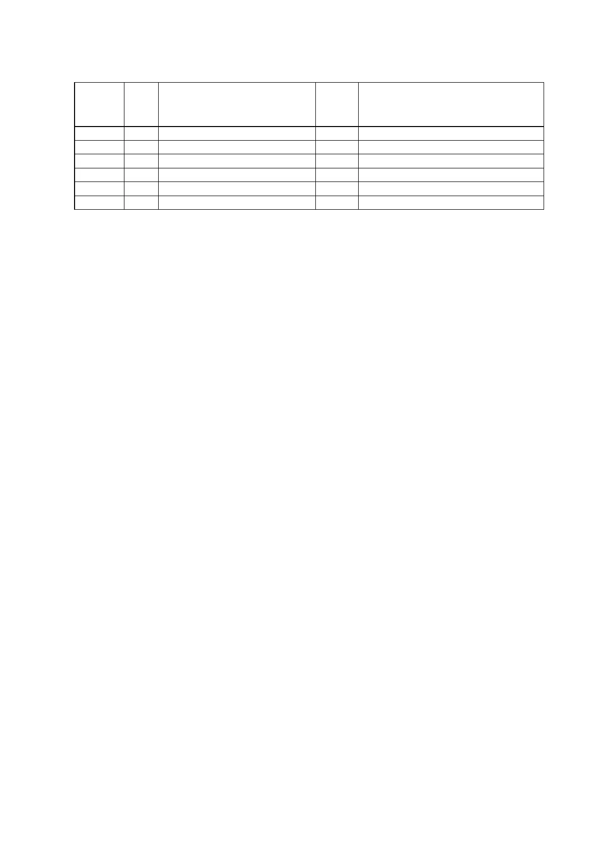
PROCEDURE AFTER REPLACING THE MICROPROCESSOR, ETC.
The procedure after replacing the u-COM (microprocessor), ash ROM, etc. is as follows.
PCB Name Ref. No. Description
Proce-
dure after
Replace-
ment
Remark
DIGITAL IC751
R5F56108VNFP
B
SOFTWARE : Main
DIGITAL IC732
MX25L3206EM2I-12G
B
SOFTWARE : GUI ROM
DIGITAL IC773
5M80ZT100C5N
B
SOFTWARE : AUDIO PLD
DIGITAL IC782
MX25L6406EM2I-12G
B
SOFTWARE : DSP ROM
MODULE 30
CY920 MODULE (CY920 Model)
D
SOFTWARE : SBL.bcd / IMG.bcd
b
1
DIGITAL U602
MX25L25635FMI-10G (CY920 Model)
C
SOFTWARE : IMG.bcd
b
1
b
1 The rmware for the CY920 MODULE is written to the INTERNAL ROM of the CY920 and the IC803 (EXTERNAL ROM) of the DIGITAL
circuit board.
"
CY920 Error
" appears in the display if the DIGITAL PCB or the CY920 is replaced, as this results in the version of the INTERNAL ROM
differing from that of the EXTERNAL ROM.
In this case, see "Update Procedure in the Event of a CY920 Error".
(This does not require special operations such as pushing multiple buttons at the same time. The rmware also cannot be updated via
DPMS.)
Procedure after Replacement
A : The software has been written. The software is not written at the time of replacement.
B : The software has been written. The software may need to be rewritten by version updates. Check the version.
C : The software has not been written. The software needs to be written after replacement.
See "Firmware Update Procedure" for information on writing the software.
D : The software has been written. Be sure to rewrite with the latest software for your service region.
See "Firmware Update Procedure" for information on writing the software.
53

 Loading...