3.5. DIAGNOSTIC MODE (Video/Audio (signal) path conrmation mode
3.5.1. Specication
This mode is used for conrming the Video and Audio (signal) paths. (Troubleshooting)
Conrming the operation of unit can be easily done after repair.
Backup data will not be lost.
3.5.2. Starting diagnostic mode
Press the "Power operation (
X
)" button to turn on power while pressing the "STATUS" and ”ZONE3 SOURCE" buttons.
Select "1. SERVICE CHECK" and press "
ENTER
" to start the set in the Diagnostic mode.
In this mode, TUNED, STEREO and RDS are lit in FL display.
3.5.3. Canceling diagnostic mode
Turn off the power by pressing the "Power operation (
X
)" button.
3.5.4 Selecting items
Press
q
button to switch between video items and audio items.
Press
w
or
e
button to select previous or next items.
This unit remote controller
q w e q w e
audio
⇔
video previous next audio
⇔
video previous next
DIMMER CURSOR LEFT CURSOR RIGHT SLEEP CURSOR LEFT CURSOR RIGHT
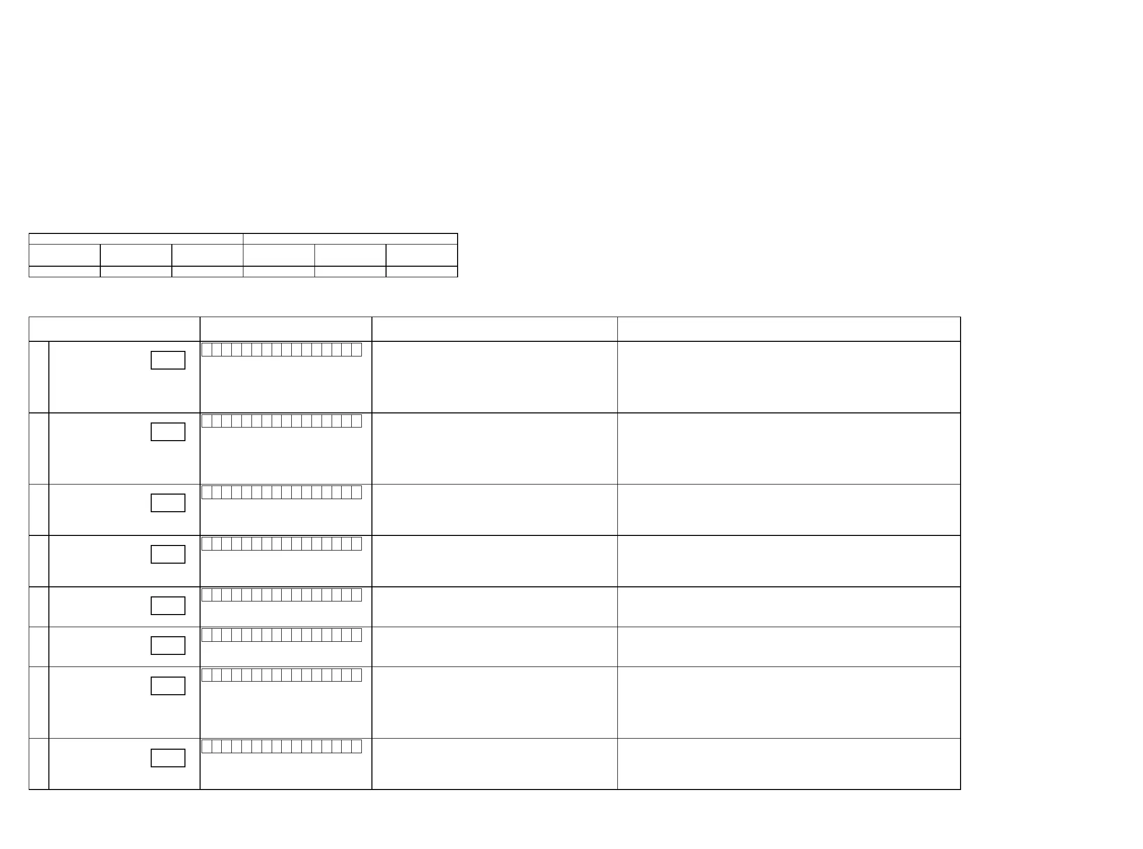
3.5.5 Video system conrmation items
g. XX: Refer to the block diagram of the g.XXth.
Conrmation item FL display
settings Contents of conrmationRemarks
V01
Analog Video (signal) Path
V 0 1 : V I D E O P A S S
Input Source : CBL/SAT
Video Convert(IP Scaler) : OFF, All sources
MAIN ZONE : ON
ZONE2 : ON
ZONE3 : OFF
·CVBS input
⇒
CVBS output
·CVBS input
⇒
CVBS RECOUT (MEDIA PLAYER)
·CVBS input
⇒
CVBS ZONE2
·Component input
⇒
Component output
·Component input
⇒
Component ZONE2
·ETHERNET (CVBS) input
⇒
CVBS output
(
b
As the input source, you can switch from CBL/SAT to other ones.)
V02
video convert
(analog or HDMI
⇒
HDMI)
V 0 2 : V . C O N V E R T
Input Source : CBL/SAT
Video Convert(IP Scaler) : ON, All sources
IP Scaler : "Analog&HDMI", All sources
Resolution : "Auto", All sources
MAIN ZONE : ON
ZONE2 : OFF
ZONE3 : OFF
·CVBS input
⇒
IP Scaler Through
⇒
HDMI output
·Component input
⇒
IP Scaler Through
⇒
HDMI output
·HDMI input
⇒
IP Scaler Through
⇒
HDMI output
·ETHERNET input
⇒
IP Scaler Through
⇒
HDMI output
b
Conrm the input pass one by on.
(
b
As the input source, you can switch from CBL/SAT to other ones.)
V03
HDMI (signal) Path
(Main Zone)
V 0 3 : H D M I P A S S
Input Source : CBL/SAT
Video Convert (IP Scaler) : OFF , All Sources
MAIN ZONE : ON
ZONE2 : OFF
ZONE3 : OFF
·HDMI input
⇒
HDMI output
(
b
As the input source, you can switch from CBL/SAT to other ones.)
V04
HDMI CEC
V 0 4 : H D M I C E C
Input Source : CBL/SAT
HDMI Control : ON
MAIN ZONE : ON
ZONE2 : OFF
ZONE3 : OFF
·When the power supply of a TV is put in the standby mode, make sure that the power supply
of this unit is also put in the standby mode.
·To check ARC path, switch the input source to "TV AUDIO".
(
b
As the input source, you can switch from CBL/SAT to other ones.)
V05
HDMI audio
(audio: AVR)
V 0 5 : H . A U D I O - A V R
Input Source : CBL/SAT
HDMI Control : OFF
HDMI Audio : AVR
·HDMI input(PCM , DolbyDigital , DTS)
⇒
Speaker output
·HDMI input(HD audio)
⇒
Speaker output
(
b
As the input source, you can switch from CBL/SAT to other ones.)
V06
HDMI audio
(audio: TV)
V 0 6 : H . A U D I O - T V
Input Source : CBL/SAT
HDMI Control : OFF
HDMI Audio : TV
·HDMI input(PCM , DolbyDigital , DTS)
⇒
HDMI output (audio output from connected TV)
(
b
As the input source, you can switch from CBL/SAT to other ones.)
V07
GUI menu
V 0 7 : G U I M E N U O N
Input Source : CBL/SAT
Video Convert(IP Scaler) : ON, All sources
IP Scaler : "Analog&HDMI", All sources
Resolution : "AUTO", All sources
MAIN ZONE : ON
ZONE2 : OFF
ZONE3 : OFF
·GUI display
⇒
HDMI output
(
b
As the input source, you can switch from CBL/SAT to other ones.)
V08
HDMI (signal) Path
(ZONE2)
V 0 8 : Z O N E 2 H D M I
Input Source : CBL/SAT
ZONE2 Source : Source
MAIN ZONE : ON
ZONE2 : ON
ZONE3 : OFF
·HDMI input (ZONE2 Function)
⇒
HDMI output (ZONE2)
(
b
As the input source, you can switch from CBL/SAT to other ones.)
g.01
g.02
g.03
g.04
g.05
g.06
g.07
g.08
28

 Loading...