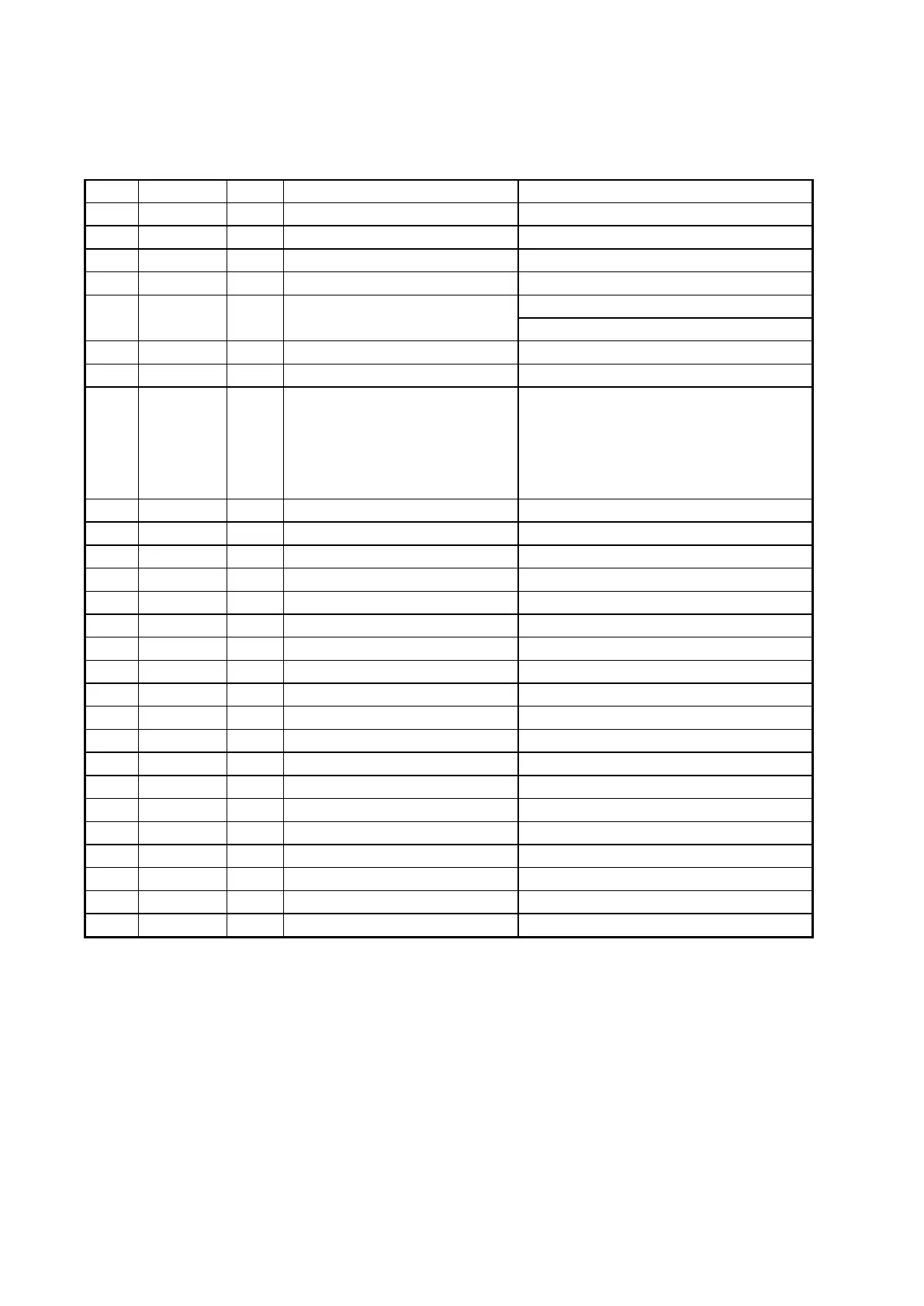
100
101 GP30 B General Purpose IO 30 CDDSP BCLK0
102 GP31 B General Purpose IO 31 CDDSP DATA0
103 GP32 B General Purpose IO 32 CDDSP LRCK0
104 GP33 B General Purpose IO 33 SBDT0
106 GP35 B General Purpose IO 35
Timer0 Output
External Interrupt 10
107 GP36 B General Purpose IO 36 External UCLK
108 RESETN I System Reset
109 NTRST I
JTAG NRST Input
When NTRSR is used for Reset of
JTAG, the external pull-up resistor
(48kΩ) has to be connected with
this pin.
110 IOVSS33 P I/O Ground
111 TEST I Test
112 XI I System clock input
113 XO O System clock output
115 IOVSS33 P I/O Ground
116 USBVDD33 P USB Power supply (3.3V)
117 USBDP B USB D+
118 USBDM B USB D-
119 USBVSS33 P USB Ground (3.3V)
120 PLL3VSS12 P PLL3 Ground (1.2V)
121 PLL3VDD12 P PLL3 Power supply (1.2V)
122 PLL2VSS12 P PLL2 Ground (1.2V)
123 PLL2VDD12 P PLL2 Power supply (1.2V)
124 PLL1VSS12 P PLL1 Ground (1.2V)
125 PLL1VDD12 P PLL1 Power supply (1.2V)
126 ADIN4 I ADC analog input[4]
127 ADIN3 I ADC analog input[3]
Note: Pin type ‘D’ means open drain output
 Loading...