99
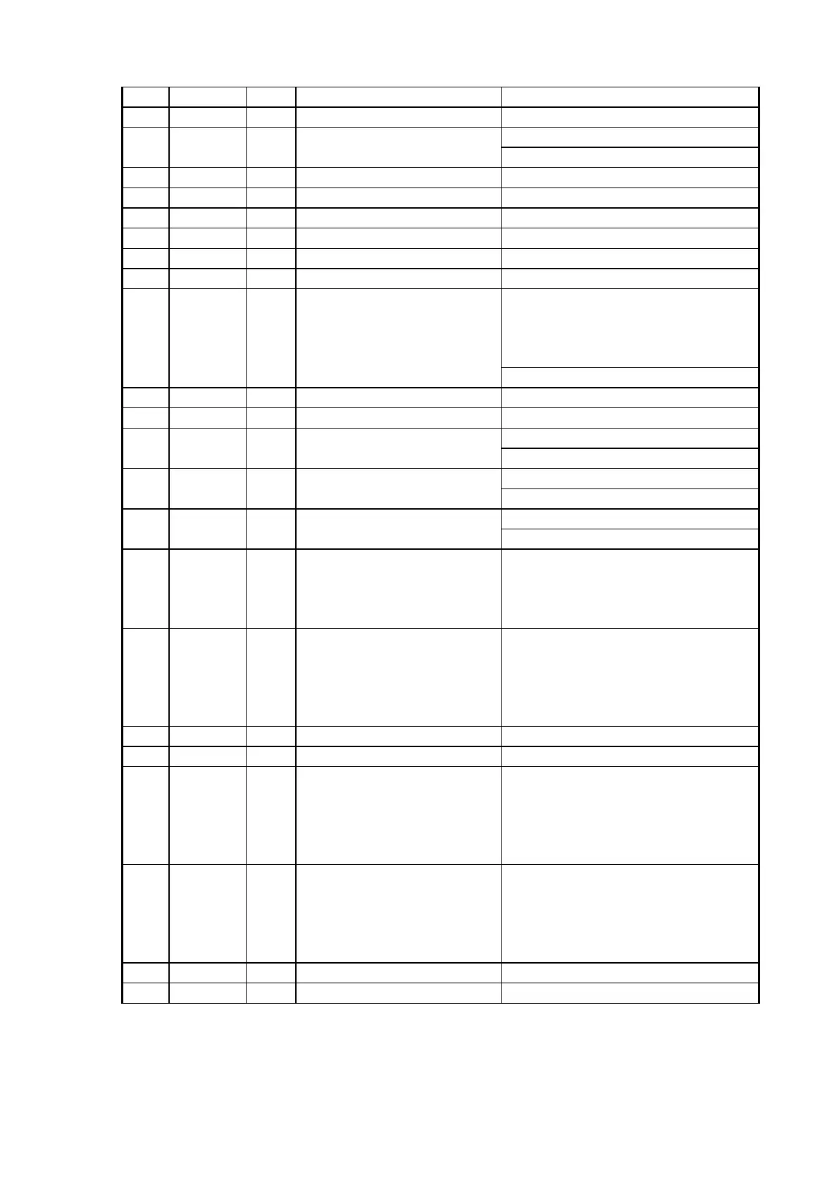
78 GP19 B General Purpose IO 19 SPI1 MISO
79 GP20 B General Purpose IO 20 SPI1 MOSI
80 GP21 B General Purpose IO 21
External Interrupt 3
SPI2 CS
Audio serial data for external DAC
82 IOVDD33 P I/O Power supply (3.3V)
83 IOVSS33 P I/O Ground
84 DMCK O Master clock for external DAC
85 DBCK O Audio serial data Bit clock
86 DLRCK O Audio serial data frame clock
87 GP22 B General Purpose IO 22
Chip Select 2
When GP22 is used for CS2, the external
pull-up resistor (48 kΩ) has to be connected
with this pin
External Interrupt 4
88 GP23 B General Purpose IO 23 HUART1 DI
89 GP24 B General Purpose IO 24 HUART1 DO
90 GP25 B General Purpose IO 25
SPI2 CK
91 GP26 B General Purpose IO 26
External Interrupt 6
SPI2 MISO
92 GP27 B General Purpose IO 27
External Interrupt 7
SPI2 MOSI
93 GP28 B General Purpose IO 28
Wake-UP
When GP28 is used for WAKE-UP signal
input pin, the external pull-down resistor
(48kΩ) has to be connected with this pin.
94 TDI B
JTAG TDI input
When GP43is used for TDI of
JTAG, the external pull-up resistor
(48kΩ) has to be connected with
this pin.
General Purpose IO 43
95 VDD12 P Digital power supply (1.2V)
96 VSS12 P Digital Ground
97 TDO B
JTAG TDO Output
When GP44 is used for TDO of
JTAG, the external pull-up resistor
(48kΩ) has to be connected with
this pin.
General Purpose IO 44
98 TMS B
JTAG TMS input
When GP45 is used for TMS of
JTAG, the external pull-up resistor
(48kΩ) has to be connected with
this pin.
General Purpose IO 45
99 TCK I JTAG Clock Input
100 GP29 B General Purpose IO 29 CDDSP SCOR0
 Loading...