12
DISASSEMBLY
• Remove each part in the order of the arrows below.
• Reassemble removed parts in the reverse order.
• Read "Precautions During Work" before reassembling removed parts.
• If wire bundles are removed or moved during adjustment or part replacement, reshape the wires after completing the
work. Failure to shape the wires correctly may cause problems such as noise.
Explanatory Photos for“ DISASSEMBLY”
• The angles from which the photos are taken are shown by “Photo angle: A, B, C, D“ .
• See the diagram below about the shooting direction of each photograph.
• Photographs with no shooting direction indicated were taken from the top of the set.
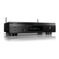
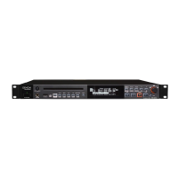
• The photograph is DNP-730AE E1C
.
The viewpoint of each photograph
(Shooting direction) Top view
Front side
Shooting
direction: D
Shooting
direction: C
↑Shooting direction: A↑
↓Shooting direction: B↓
FRONT PANEL ASSY
See "DISASSEMBLY
1. FRONT PANEL ASSY"
and "EXPLODED VIEW"
FRONT PCB
(Ref. No. of EXPLODED VIEW : P2)
LED PCB
(Ref. No. of EXPLODED VIEW : P1)
KEY PCB
(Ref. No. of EXPLODED VIEW : P5)
USB PCB
(Ref. No. of EXPLODED VIEW : P6)
SMPS PCB
See "DISASSEMBLY
3. SMPS PCB "
and "EXPLODED VIEW"
SMPS PCB
(Ref. No. of EXPLODED VIEW : P3)
WIFI MODULE
See "DISASSEMBLY
4.WIFI MODULE"
and "EXPLODED VIEW"
WIFI MODULE
TOP COVER
MAIN PCB
See "DISASSEMBLY
2. MAIN PCB "
and "EXPLODED VIEW"
MAIN PCB
(Ref. No. of EXPLODED VIEW : P4)

 Loading...