R
Robert McgeeSep 23, 2025
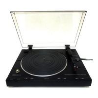
Why is track information acquired only for some files of a recorded album on my Denon DP-200USB?
- JJames DuncanSep 23, 2025
When searching MusicID, select “Identify tracks as albums”. Even if the search finds only one matching track in the album, you can obtain the track information from the album list manually.