87
RCD-CX1
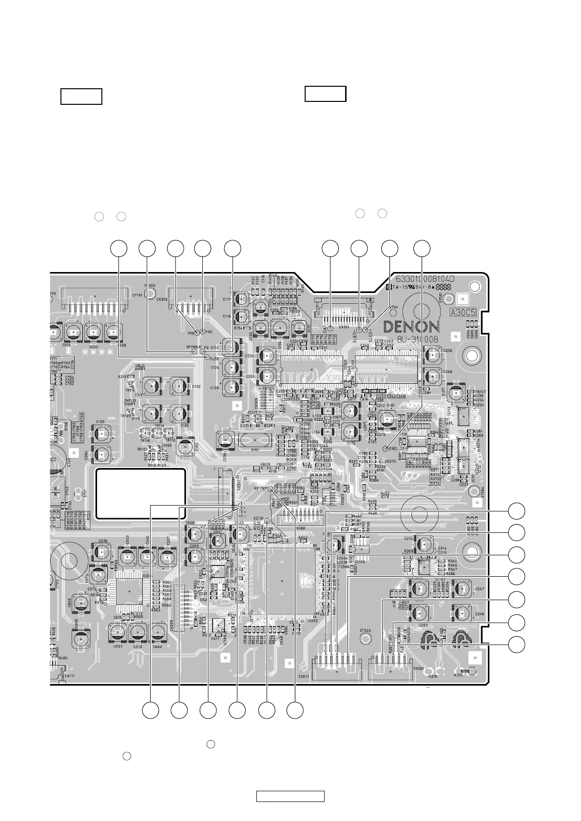
各部の波形と測定方法
メイン基板の波形チェックを行うためにはオシロスコー
プの GND(
-
) プローブを "Vref" ポイントに接続します。
測定ディスク: SACD/DACTestDisc
CD/TCD-784
(テストポイントとプローブ間に延長ワイヤを使用する
のがより良い方法です。)
・ HF 波形を観測する場合、できるだけ短い延長ワイヤ
を使用してください。
・ HF 波形がノイズで不明瞭、またはアイパターンが識
別不能の場合は Iop 測定後にトラバースユニットを交
換してください。
・ ポイント 〜 は、下図のポイントで測定してくだ
さい。
注 意
1 22
MEASURING METHOD AND WAVEFORMS
To check the waveforms on the Main P.W.B., the GND (
-
) probe of the oscilloscope to “Vref” point.
(Except for lnner SW, TRVSW)
Measuring Disc: SACD/DAC Test Disc
CD/TCD-784
(It is better to use wires for extending between the probe
and test points.)
• When watching the HF waveform, use the extending
wire as short as possible.
• When HF waveform is noisy or cannot discriminate the
eye-pattern, replace the Traverse Unit after measuring
the lop.
• Point 〜 is measured with the point shown below.
NOTES
1 22
1710
4
13256 143
11 158
21
22
20
16
19
18
17
1 9
12
8U-310008 DRIVE/SACD/DAC P.W.B. Unit : Component Side
* Reference voltage of ⑬,⑯~ is GND_D1 ⑮ , and reference voltage of other point is VC16 ⑭ .
*⑬、⑯〜 の基準電圧は GNDD1 ⑮で、他のポイントの基準電圧は VC16 ⑭です。
22
22
 Loading...


