aXcs
®
Wall/Cabinet Unit 15
Section III Installation
4. Connect the syringe to the valve body and
install the nozzle tube assembly following the
instructions in the owners manual supplied
with the syringe.
— NOTICE —
After completing all tubing installation, make
certain the tubing is properly connected and
does not interfere with the closing of the
delivery head cover.
— WARNING —
Before connecting the optional field installed
chipblower, make sure the unit is OFF so
that no air is present at the foot control.
Chipblower (Optional)
Flat Head
Screws (7)
Chipblower
1. Remove the seven flat-head screws from the
base of the foot control and disassemble.
2. Remove the chip air line on the foot control
tubing from the tee fitting.
NOTE: Secure all connections using the tubing
clamps provided.
3. Connect a six-inch section of the clear 1/8"
tubing included in the kit to the tee fitting and
rotate it around the drive air valve.
4. Attach the clear 1/8" tubing to the A port of
the shuttle valve.
WET/DRY
Toggle Valve
3"
Tubing
Chip Air
Valve
Assembly
Shuttle Valve
6" Tubing
Drive
Air Valve
6" Clear
Tubing
Te e
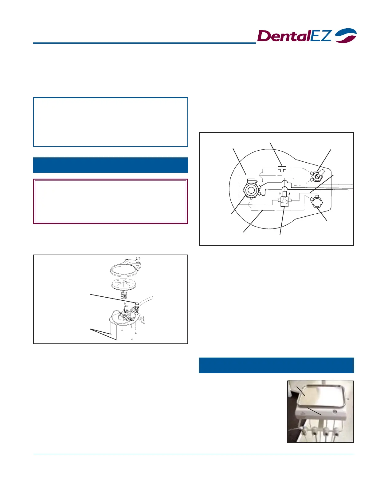
Delivery Head Tray w/Pad
5. Install the chip air valve assembly on the foot
control base and secure it using the three flat-
head screws included in the kit.
6. Connect a three-inch section of tubing to the
B port of the shuttle valve and chip air valve.
7. Attach the chip air line on the foot control
tubing to the C port of the shuttle valve.
8. Remove the hex plug from the drive air valve.
9. Place a plastic washer on the threaded end of
the barb fitting.
10. Install the barb fitting into the drive air valve.
11. Route a six-inch section of tubing from the
drive air valve to the remaining barb on the
chip air valve assembly.
12. Reassemble the foot control and replace the
seven flat-head screws
1. Place the pad on top
of the delivery head.
Then position the pad
so the tray can center
properly.
2. Place the tray on the
pad.
Tr ay
Pad
 Loading...