aXcs
®
Wall/Cabinet Unit 17
Section IV Testing
e. Allow water to flow freely from all tubings
for approximately two minutes to ensure
all air has escaped.
3. Attach the handpieces to the tubing as
follows:
a. Slide the connector nut down along the
tubing to expose the handpiece adaptor.
b. Carefully align and insert the handpiece
base into the adaptor.
c. Replace and tighten the connector nut to
complete installation.
e. Using a slotted screwdriver, turn the air
pressure adjustment screw on the control
valve of the appropriate handpiece
(counterclockwise to increase pressure, clockwise
to decrease pressure) until the hand-piece
manufacturer's correct specification
registers on the pressure gauge.
3. Repeat a. through e. in Step 2 to set the
pressure for each handpiece.
NOTE: If a low-speed handpiece is required, slide the
coolant air and water restrictor over the lines on the
appropriate control valve.
Flush Valve
1. Remove the handpiece from its holder.
2. Activate the flush toggle valve.
3. Operate each handpiece for 30 seconds into a
cuspidor, sink or open vacuum line.
Air Pressure
1. Flip the toggle valve from WET to DRY at
the foot control.
2. To adjust the individual handpiece drive air
pressure to the manufacturer's specifications
do the following procedure:
a. Remove the handpiece from its holder.
b. Insert an air pressure gauge as indicated in
the illustration above.
c. Hold the handpiece, fully depress the foot
control and observe the amount of air
pressure delivered to the handpiece.
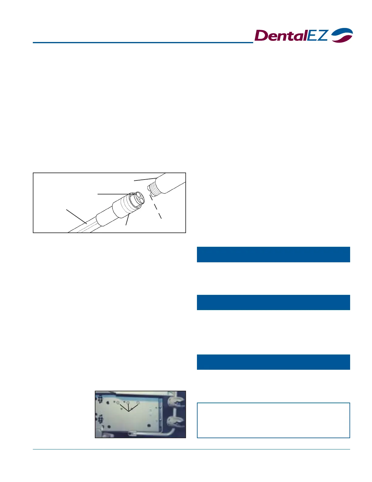
d. Locate the air pressure adjustment screws
Tubing
Adaptor
Handpiece
Nut
(Insert Air Pressure
Gauge Here)
Air Pressure
Adjustment
Screws
— NOTICE —
After all final testing is complete, install
the USC cover using four #10 screws.
Syringe
Chipblower (Optional)
Fiber Optics (Optional)
If the unit is equipped with a syringe, first depress the
air button and then the water button to test the flow.
If the DWM/DCM is equipped with a chip air foot
control, a burst of air should be delivered to the
handpiece when the chip air valve is depressed.
Follow the test procedures outlined in the instructions
included in each fiber optic handpiece package.
on the
bottom
of the
delivery
head
chassis.
 Loading...