7.1 6 95-8242
RESPONSE TIME—
Response to a saturating (high intensity) UV source is
typically 10 milliseconds for the zone and alarm outputs
and 150 milliseconds for the fire logic outputs when
sensitivity is set for 8 cps and time delay is set for 0
seconds.
OUTPUT CIRCUIT RATINGS—
Open collector solid state output is rated 100 milliamperes
dc at 60 volts dc. Lead monitoring is provided by an
internal 100 kilohm resistor from output to ground. External
equipment that can generate transients when switching
(such as relays) must have a transient suppression device
(diode) connected across the coil at the time of installation
to safeguard the output transistors against possible
damage. See the “Installation” section for details.
POWER CONSUMPTION (Controller and 16 Detectors)—
Standby: 1.5 watts typical, 1.7 watts maximum.
Fire: 15wattstypical,16.5wattsmaximum.
WIRING REQUIREMENTS—
The detector wiring must be a minimum of 22 gauge with
a minimum voltage rating of 600 volts rms. (22 gauge
copper wire has a diameter of 0.6439 mm or 0.02535
inch. Its cross section is 0.3255 mm
2
or 0.0005 in
2
. Its
resistance is 16.14 ohm/1000 ft. or 53.0 ohm/km.) The
R7404 Controller will accommodate up to 16 detectors.
The detectors can be located up to 2000 feet (600
meters) from the controller. Shielded cable is required
for the “B” (signal) leadwires. As with any field device,
shielded cable on all wires provides maximum protection
fromRFI/EMIsources.
SHIPPING WEIGHT (APPROXIMATE)—
Pounds Kilograms
Controller 2.5 1.12
Detector (aluminum) 1.25 0.56
(stainless steel or brass) 2.25 1.0
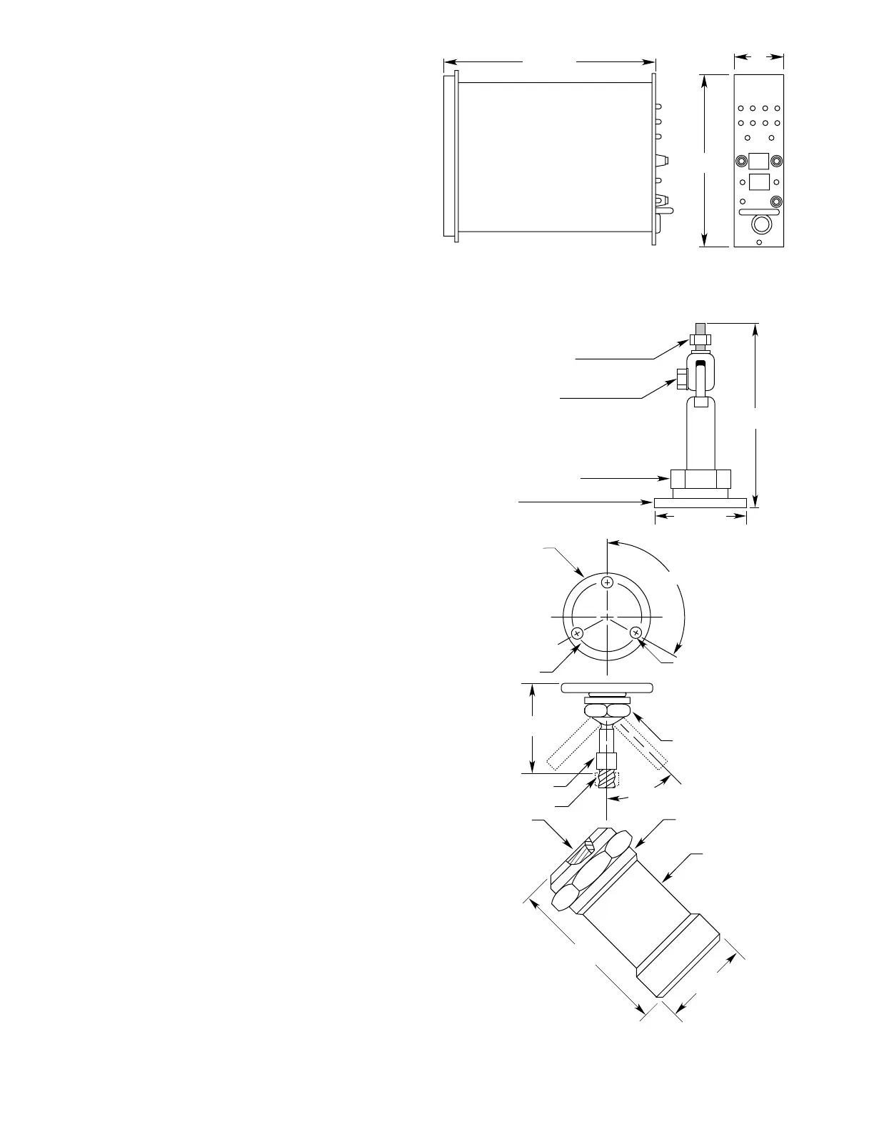
DIMENSIONS—
Refer to Figure 3 for dimensions of the controller and
Figure4 for the detectorand swivel mountingbrackets.
Figure5 shows the dimensionsof the Q4004 Mounting
Cage. Cages that hold fewer devices are also available.
CONE OF VISION—
The C7050 Detector has a nominal 90 degree cone of
vision with the highest sensitivity along its central axis.
SeeFigure7.
DETECTOR ENCLOSURE MATERIALS—
Models are available in anodized copper-free aluminum,
nickel-plated brass, or 316 stainless steel.
9.5 (242 MM)
7.0
(177 MM)
2.0
(50MM)
F234
Figure 3—Controller Dimensions in Inches (Millimeters)
POSITIONING SWIVEL NUT
0.25 (6.4 MM) DIAMETER (3)
DETECTOR HOUSING
2-1/2 (64 MM) DIAMETER
TERMINAL CAP
2.00 (50.8 MM) DIAMETER
1/2 – 14 NPT
3/4 – 14 NPT
M20 x 1.5
M25 x 1.5 – 6H
Pg 16
5/16 – 18 UNC – 2A
DETECTOR LOCK NUT
CONDUIT OPTIONS:
OPTIONAL SWIVEL
MOUNTING BRACKET
(Q9001B, FOR ALUMINUM ONLY)
120
o
± 2
o
(2)
45
o
(2)
2-1/2
(64 MM)
2-1/2
(64 MM)
4-3/4
(121 MM)
G0 121
5-1/4 INCHES
(133 MM)
2-1/2 INCHES
(64 MM)
MOUNTING BASE
1/2 INCH NUT USED TO ADJUST
ELBOW TO DESIRED ANGLE
1-3/8 INCH NUT USED TO ROTATE
SWIVEL/DETECTOR ASSEMBLY TO DESIRED POSITION
3/4 INCH NUT USED TO SECURE
DETECTOR TO SWIVEL MOUNT
B1323
Q9001H – USE FOR MOUNTING NICKEL/BRASS
AND STAINLESS STEEL C7050 DETECTORS
Figure 4—Detector Dimensions in Inches (Millimeters)