95-8768102.1
24 VDC
mA
PLC
–
+
600 Ω MAX
AT 24 VDC
–
+
F2256
O
i
TEST
1
9
8
7
6
5
4
3
2
1
19
18
17
16
15
14
13
12
11
mA + mA –
mA + REF mA
–
REF
+Vin
–Vin
+Vin
–Vin –Vin
29
28
27
26
25
24
23
22
21
MAN O
i
X3302 IR DETECTOR
SPARE
SPARE
RS-485 A
RS-485 B
COM AUX
N.O. AUX
N.C. AUX
COM FIRE
N.O. FIRE
N.C. FIRE
COM FIRE
N.O. FIRE
N.C. FIRE
COM FAULT
N.O. FAULT
COM FAULT
N.O. FAULT
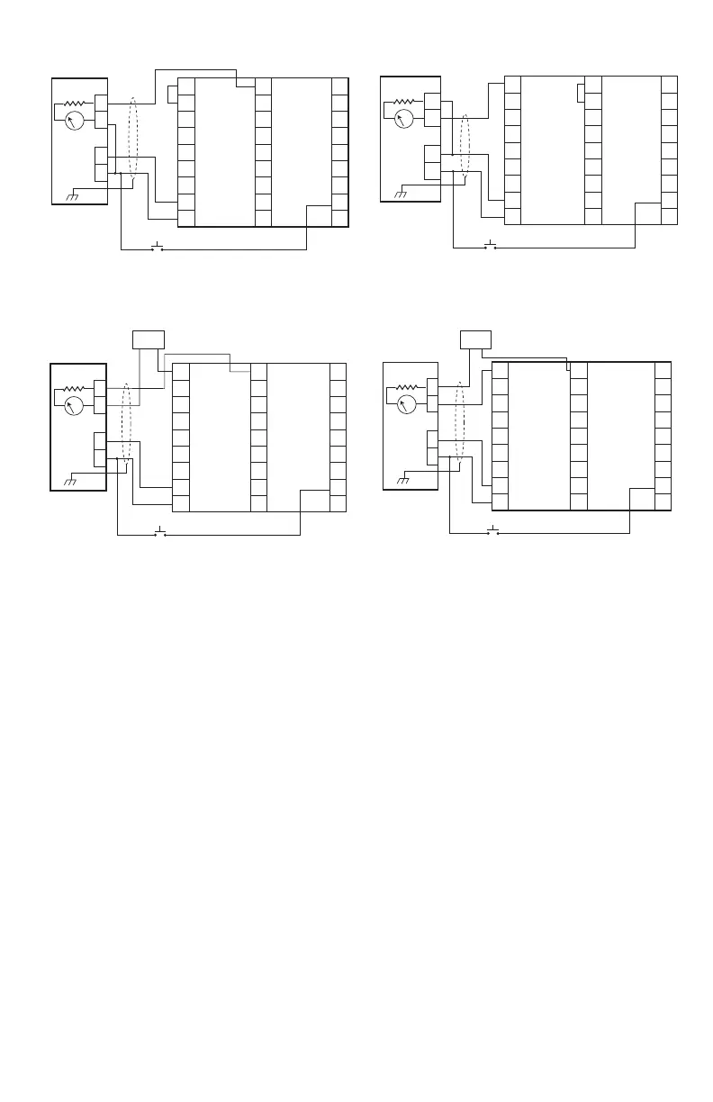
Figure10—X3302 Detector Wired for Non-Isolated 0 to 20 mA
Current Output (Sourcing)
24 VDC
mA
PLC
–
+
600 Ω MAX
AT 24 VDC
–
+
F2257
O
i
TEST
1
9
8
7
6
5
4
3
2
1
19
18
17
16
15
14
13
12
11
29
28
27
26
25
24
23
22
21
mA +
mA + REF
+Vin
–Vin
COM FIRE
N.O. FIRE
N.C. FIRE
COM FAULT
N.O. FAULT
COM FIRE
N.O. FIRE
N.C. FIRE
COM FAULT
N.O. FAULT
+Vin
–Vin –Vin
MAN O
i
SPARE
SPARE
RS-485 A
RS-485 B
COM AUX
N.O. AUX
N.C. AUX
mA –
mA
–
REF
Figure11—X3302 Detector Wired for Non-Isolated 0 to 20 mA
Current Output (Sinking)
24 VDC
mA
PLC
–
+
600 Ω MAX
AT 24 VDC
–
+
F2258
O
i
TEST
1
9
8
7
6
5
4
3
2
1
19
18
17
16
15
14
13
12
11
29
28
27
26
25
24
23
22
21
X3302 IR DETECTOR
–
+
24 VDC
mA +
mA + REF
+Vin
–Vin
COM FIRE
N.O. FIRE
N.C. FIRE
COM FAULT
N.O. FAULT
COM FIRE
N.O. FIRE
N.C. FIRE
COM FAULT
N.O. FAULT
mA –
mA
–
REF
+Vin
–Vin –Vin
MAN O
i
SPARE
SPARE
RS-485 A
RS-485 B
COM AUX
N.O. AUX
N.C. AUX
Figure12—X3302 Detector Wired for Isolated 0 to 20 mA
Current Output (Sourcing)
24 VDC
mA
PLC
–
+
600 Ω MAX
AT 24 VDC
–
+
F2259
O
i
TEST
1
9
8
7
6
5
4
3
2
1
19
18
17
16
15
14
13
12
11
29
28
27
26
25
24
23
22
21
X3302 IR DETECTOR
–
+
24 VDC
mA +
mA + REF
+Vin
–Vin
COM FIRE
N.O. FIRE
N.C. FIRE
COM FAULT
N.O. FAULT
mA –
mA
–
REF
COM FIRE
N.O. FIRE
N.C. FIRE
COM FAULT
N.O. FAULT
+Vin
–Vin –Vin
MAN O
i
SPARE
SPARE
RS-485 A
RS-485 B
COM AUX
N.O. AUX
N.C. AUX
Figure13—X3302 Detector Wired for Isolated 0 to 20 mA
Current Output (Sinking)
NOTES: 1. INDIVIDUAL MANUAL o
i
TEST SWITCHES CAN BE
INSTALLED REMOTELY OR A DETECTOR SELECTOR AND
ACTIVATION SWITCH CAN BE INSTALLED AT THE FIRE
PANEL. TEST SWITCHES ARE NOT SUPPLIED.
EQP Model
1. Connect external wires to the appropriate
terminals inside the device junction box,
shown in Figure 15. See Figure 16 for
terminal identification.
2. Connect the shield of the power cable to
“earth ground” at the power source.
3. Connect shields for the LON cable as
indicated. See Figure 14.
NOTE
DO NOT ground any shields at the detector
housing.
4. With input power disconnected, set the
device network address (see the “Setting
Device Network Addresses” section of this
manual for the switch setting procedure).
5. Check all field wiring to be sure that the
proper connections have been made.
6. Replace and securely tighten the device
cover before applying input power.
7. Make the final sighting adjustments and
use a 14 mm hex wrench to ensure that the
mounting arm assembly is tight.
NOTE
Refer to the Eagle Quantum Premier®
system manual, number 95-8533, for
information regarding power requirements,
network communication cable
requirements, and conguration.