95-8768132.1
STARTUP PROCEDURE
When installation of the equipment is complete,
perform the “Fire Alarm Test” below.
FIRE ALARM TEST
1. Disable any extinguishing equipment that is
connected to the system.
2. Apply input power to the system.
3. Initiate an
o
i
test (see “Magnetic
o
i
/ Manual
o
i
” under Optical Integrity in the Description
section of this manual).
4. Repeat this test for all detectors in the
system. If a unit fails the test, refer to the
“Troubleshooting” section of this manual.
5. Verify that all detectors in the system are
properly aimed at the area to be protected.
(The Q1201C Laser Aimer is recommended
for this purpose.)
6. Enable extinguishing equipment when the
test is complete and the detectors have
returned to normal operation.
TROUBLESHOOTING
WARNING
The sensor module (“front” half of the detector)
contains no user serviceable components and
should never be tampered with.
1. Disable any extinguishing equipment that is
connected to the unit.
2. Inspect the viewing windows for contamination
and clean as necessary. The detector is relatively
insensitive to airborne contaminants, however,
thick deposits of ice, dirt, or oil will reduce
sensitivity. (Refer to the “Maintenance” section of
this manual for complete information regarding
cleaning of the detector viewing windows.)
3. Check input power to the unit.
4. If the fire system has a logging function,
check the fire panel log for output status
information. See Table 3 for information
regarding 0–20 mA output.
5. The use of the Enhanced Flame Inspector
cable and software from Det-Tronics can be
considered to determine the nature of the fault
condition. Refer to instruction manual 95-8751
for more information. To order an Enhanced
Flame Inspector, see Accessories within the
Ordering Information section of this manual.
6. Turn off the input power to the detector and
check all wiring for continuity. Important:
Disconnect wiring at the detector before
checking system wiring for continuity.
7. If all wiring checks out and cleaning of the o
i
reflector plate/window did not correct the fault
condition, check for high levels of background
IR radiation by covering the detector with the
factory supplied cover or aluminum foil. If the
fault condition clears within six minutes or
less, extreme background IR is present. Re-
adjust the view of the detector away from the
IR source or relocate the detector.
8. Remove the factory supplied cover or
aluminum foil from the detector and
verify the detector has returned to normal
operation before enabling any extinguishing
equipment connected to the unit.
If none of these actions corrects the problem,
please contact your local Det-Tronics
Representative or alternatively you may contact
Det-Tronics Technical Support by calling 1-800-
165-3473 to obtain assistance.
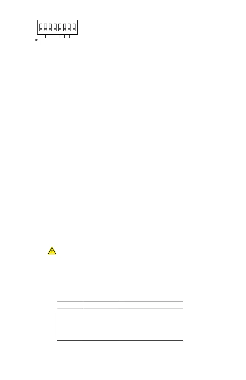
1 2 3 4 5 6 7 8
1 2 4 8 16 32 64 128
ON
NODE ADDRESS EQUALS THE ADDED VALUE
OF ALL CLOSED ROCKER SWITCHES
A2190
BINARY
VALUE
CLOSED = ON
OPEN = OFF
Figure 18
—
Address Switches for X3302
Table3—Current Level Output Troubleshooting Guide
Current Level
(±0.3 mA)
Status Action
0 mA Power Fault Check system wiring
1 mA General Fault Cycle power
1
2 mA o
i
Fault Clean windows
2
3 mA
High Background IR Fault
Remove IR source or aim detector away from IR source
4 mA Normal Operation
20 mA Fire Alarm
1
If fault continues, return device to factory for repair.
2
See “Maintenance” section for cleaning procedure.
NOTE: For additional troubleshooting guides, refer to the Flame Inspector Monitor manual (95-8581).