95-876862.1
• The detector must be mounted on a rigid
surface in a low vibration area.
• Dense fog, rain or ice can absorb IR radiation
and reduce the sensitivity of the detector. To
ensure optimum performance, be certain that the
internal optical heater is enabled on detectors
that are used in applications where snow, ice,
and/condensation are likely to occur.
• Although IR detectors are less affected
by smoke than other detectors, the
X3302 should not be placed where rising
combustion products can obscure its vision.
If smoke is expected before fire, smoke or
other alternative detectors should be used
in conjunction with the X3302. For indoor
applications, if dense smoke is expected
to accumulate at the onset of a fire, install
the detector on a side wall at least a few
feet (approximately 1 meter) down from the
ceiling.
• If possible, fire tests can be conducted to verify
correct detector positioning and coverage.
• For ATEX/IECEx installations, the X3302
detector housing must be electrically
connected to earth ground.
DETECTOR ORIENTATION
Refer to Figure 2 and ensure that the
o
i
reflector
plate will be oriented as shown when the X3302
is installed and sighted. This will ensure proper
operation of the
o
i
system and will also minimize
the accumulation of moisture and contaminants
between the
o
i
reflector plate and the viewing
windows.
IMPORTANT
If removed, the
o
i
reflector plate must
be securely tightened to ensure proper
operation of the
o
i
system (40 oz./inches
[28.2 N.cm] recommended).
PROTECTION AGAINST MOISTURE
DAMAGE
It is important to take proper precautions during
installation to ensure that moisture will not come
in contact with the electrical connections or
components of the system. The integrity of the
system regarding moisture protection must
be maintained for proper operation and is the
responsibility of the installer. Verify all covers are
securely tightened upon installation.
If conduit is used, we recommend installing drains,
according to local codes, at water collection
points to automatically drain accumulated
moisture. It is also recommended to install at least
one breather, according to local codes, at upper
locations to provide ventilation and allow water
vapor to escape.
Conduit raceways should be inclined so that
water will flow to low points for drainage and
will not collect inside enclosures or on conduit
seals. If this is not possible, install conduit drains
above the seals to prevent the collection of water
or install a drain loop below the detector with a
conduit drain at the lowest point of the loop.
Conduit seals are not required for compliance
with explosion-proof installation requirements, but
are highly recommended to prevent water ingress
in outdoor applications. Units with M25 threads
must use an IP66/IP67 washer to prevent water
ingress.
WIRING PROCEDURE
Wire Size and Type
The system should be wired according to local
codes. The wire size selected should be based
on the number of detectors connected, the supply
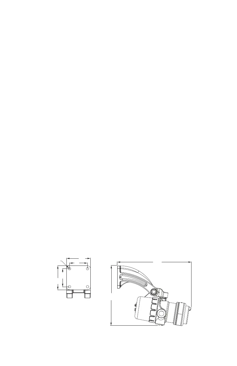
13.1
(33.3)
10.6
(27.0)
4.0
(10.2)
4.0
(10.2)
3.0
(7.6)
3.0
(7.6)
4X ø0.42
(1.1)
F2069
NOTE: THIS ILLUSTRATION SHOWS THE
DETECTOR MOUNTED AT THE 10° MINIMUM.
THESE DIMENSIONS WILL CHANGE BASED
ON THE DETECTOR’S MOUNTING ANGLE.
Figure3—Q9033 Mounting Arm without Collar Attachment Dimensions in Inches (cm)
(See Figure 1 for Correct Detector Orientation.)