95-8768142.1
NOTE
It is highly recommended that a complete
spare be kept on hand for eld replacement
to ensure continuous protection.
MAINTENANCE
IMPORTANT
Periodic flamepath inspections are not
recommended, since the product is not
intended to be serviced and provides
proper ingress protection to eliminate
potential deterioration of the amepaths.
WARNING
To avoid a potential electrostatic discharge
(ESD), the painted surface of the detector
should only be cleaned with a damp cloth.
WARNING
The sensor module (“front” half of the
detector) contains no user serviceable
components and should never be tampered
with.
NOTE
Refer to the X3302 Safety manual, number
95-8720, for specific requirements and
recommendations applicable to the proper
installation, operation, and maintenance of
all SIL-Certied X3302 Flame Detectors.
To maintain maximum sensitivity and false
alarm resistance, the viewing windows of the
X3302 must be kept relatively clean. Refer to the
following procedure for cleaning instructions.
CLEANING PROCEDURE
CAUTION
Disable any extinguishing equipment that is
connected to the unit to prevent unwanted
actuation.
To clean the windows and
o
i
reflector plate, use
the window cleaner (p/n 001680-001) and a soft
cloth, cotton swab, or tissue and refer to the
following procedure.
1. Disable any extinguishing equipment that
is connected to the unit.
2. Since the X3302 is less affected by
contamination than other detectors, removal
of the
o
i
reflector plate is needed only under
extreme conditions. In addition, it is not
necessary to achieve perfect cleanliness,
because IR is not significantly absorbed
by slight films of oil and/or salt. If a fault
condition is still indicated after cleaning,
remove and clean the
o
i
reflector plate
using the
o
i
Reflector Plate Removal and
Replacement procedure.
3. Clean all three viewing windows and
reflector surfaces thoroughly. Use a
cotton swab and the Det-Tronics window
cleaning solution. Use Isopropyl alcohol for
contaminations that the Det-Tronics window
cleaning solution can not remove.
IMPORTANT
When used in extreme environments, the
reective surface of the detector
o
i
reector
plate may eventually deteriorate, resulting
in reoccurring
o
i
faults and the need for
o
i
reector plate replacement.
o
i
REFELCTOR PLATE REMOVAL AND
REPLACEMENT
1. Disable any extinguishing equipment that
is connected to the unit.
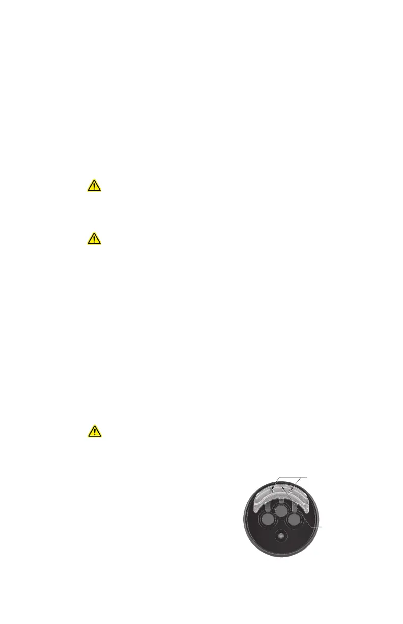
2. Loosen the two captive screws, then grasp
the o
i
reflector plate by the visor and remove
it from the detector. See Figure 19.
3. Install the new (or cleaned) o
i
reflector plate.
NOTE
When installing the stainless steel
o
i
reflector plate, ensure that the gasket is
present and correctly seated to prevent
moisture or contaminants from penetrating
behind the
o
i
reector plate. To ensure even
seating, tighten both screws equally.
LOOSEN TWO CAPTIVE SCREWS
GRASP VISOR AND
REMOVE o
i
REFLECTOR PLATE
B2106
Figure 19
—
o
i
Reector Plate Removal