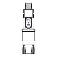
Model IR-700
IR-700 Instruction Manual Rev. 4.3 Page 15 of 46
3. Operation
3.1 Programming Magnet Operating Instructions
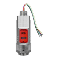
The Operator Interface of the Model 700 Series gas sensors is accomplished via two internal magnetic switches
located to either side of the LED display (see Figure 16). The two switches, labeled “PGM1” and “PGM2”,
allow for complete calibration and configuration and thereby eliminate the need for area de-classification or the
use of hot permits.
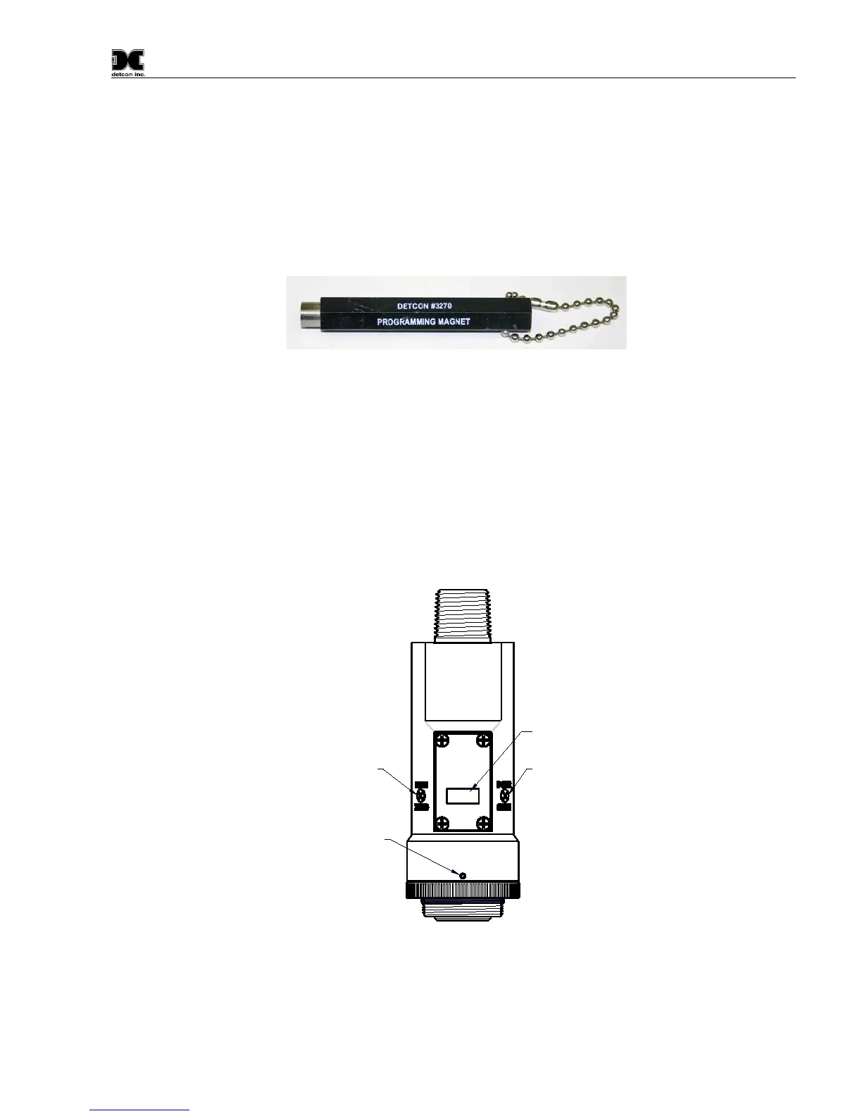
Figure 15 Magnetic Programming Tool
The magnetic programming tool (Figure 15) is used to operate the magnetic switches. Switch action is defined
as momentary contact, 3-second hold, and 10-second hold. (Hold times are defined as the time from the point
when the arrow-prompt “
“appears.) For momentary contact use, the programming magnet is briefly held over
a switch location. For 3-second hold, the programming magnet is held in place over the switch location for three
seconds. For 10-second hold, the programming magnet is held in place over the switch location for 10 seconds.
The 3 and 10 second holds are generally used to enter calibration/program menus and save new data. The
momentary contact is generally used to move between menu items and to modify set-point values. Arrows (“
”
and “
”) are used on the LED display to indicate when the magnetic switches are activated. The location of
“PGM1” and “PGM2” are shown in Figure 16.
Program Switch #1
LED Display
Program Switch #2
Splash Guard Adapter
Locking Set-Screw
detcon inc.
LEL
MODEL
IR-700
Figure 16 Magnetic Programming Switches