Model IR-700
IR-700 Instruction Manual Rev. 4.3 Page 3 of 46
1.2 Sensor Electronics Design
1.2.1 Intelligent Transmitter Module
The Intelligent Transmitter Module (ITM) is a fully encapsulated microprocessor-based package that accepts a
plug-in field replaceable combustible gas sensor and for IR-700 CO
2
sensors, a plug-in replaceable CO
2
sensor.
Circuit functions include extensive I/O circuit protection, sensor pre-amplifier, on-board power supplies,
microprocessor, LED display, magnetic programming switches, a linear 4-20mA DC output, and a Modbus™
RS-485 output. Magnetic program switches located on either side of the LED Display are activated via a hand-
held magnetic programming tool, thus allowing non-intrusive operator interface with the ITM. Calibration can
be accomplished without declassifying the area. Electrical classifications are Class I, Division 1, Groups B C
D, Class I, Zone 1, Group IIB+H
2
, and II 2G Ex d IIB+H
2
Gb.
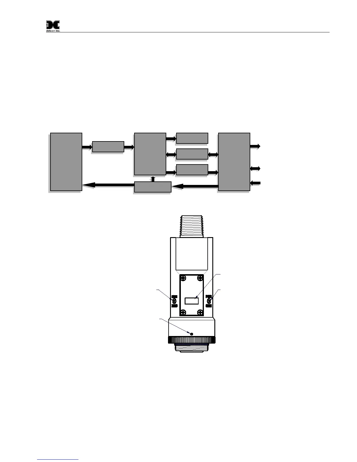
Figure 4 ITM Circuit Functional Block Diagram
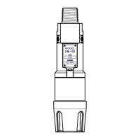
Program Switch #1
LED Display
Program Switch #2
Splash Guard Adapter
Locking Set-Screw
detcon inc.
LEL
MODEL
IR-700
Figure 5 Sensor Assembly Front View
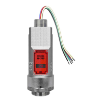
1.3 Modular Mechanical Design
The Model IR-700 Sensor Assembly is completely modular and made up of four parts (See Figure 6 for
Assembly Breakaway):
1) IR-700 Intelligent Transmitter Module (ITM)
2) Field Replaceable Plug-in Infra-Red Gas Sensor
I/O
Circuit
Protection
Micro-
Processor
Plug-In
Sensor
Element