Model IR-700
IR-700 Instruction Manual Rev. 4.3 Page 34 of 46
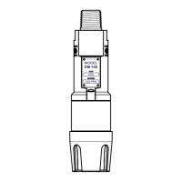
5.6 Replacement of IR-700 Sensor Assembly
Caution: Hazardous areas must be declassified before removing the junction box cover
or replacing the sensor assembly
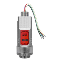
a) Disconnect all sensor wire connections at the J-Box, after removing power source.
b) Use a wrench and loosen the locking nut at the top of the ITM and unthread the ITM from the junction
box.
c) Feed the new IR-700 sensor assembly wires through the ¾” female NPT mounting hole and thread the
assembly into the J-box until tight and the ITM lens faces toward the front access point. Connect the
sensor assembly wires inside J-Box (Refer to Section 2.6, and Figure 14).
d) IR-700 sensors are factory calibrated. However, they will require an initial AutoZero and AutoSpan
(Section 3.4). They must also be configured per customer specific application requirements.