Model IR-700
IR-700 Instruction Manual Rev. 4.3 Page 19 of 46
Material Requirements:
• Detcon PN 327-000000-000 MicroSafe™ Programming Magnet
• Detcon PN 613-120000-700 700 Series Splash Guard with integral Cal Port and Calibration Wind Guard
(P/N 943-000000-000) -OR-
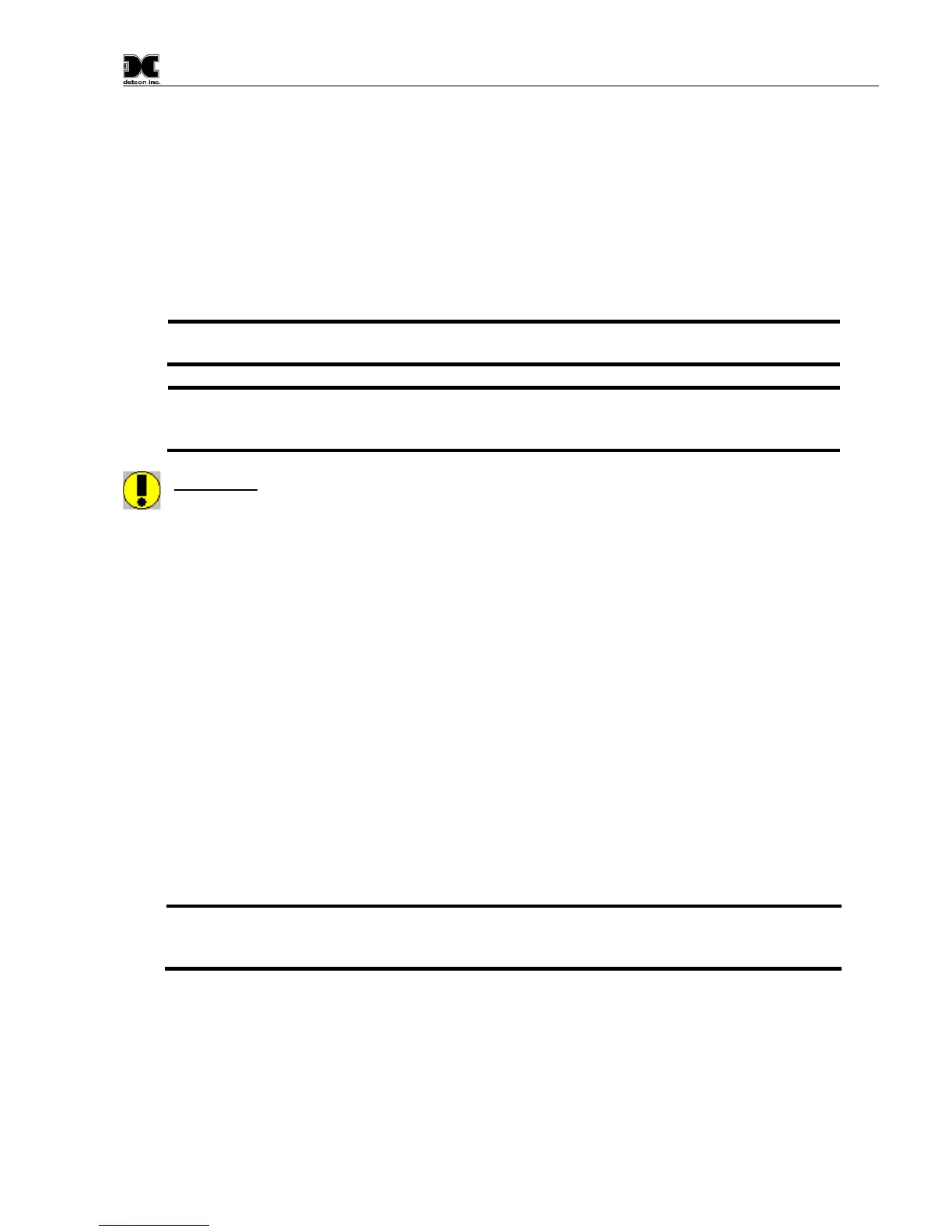
• Detcon PN 943-000006-132 Threaded Calibration Adapter
• Detcon PN 942-520124-050 50% LEL Methane in balance air (recommended for 0-100% LEL range),
or
• Detcon PN 942-520124-025 25% LEL Methane in balance air (recommended for 0-50% LEL range),
or other suitable span gas containing a certified level of % LEL concentration of common combustible
hydrocarbon gas.
NOTE 1: If the span gas is different from the measured target gas, remember to use the
appropriate Gas Factor as described in Section 3.5.4.
NOTE 2: The Calibration Wind Guard must be used when the Splashguard Adapter with
integral Cal Port is used. Failure to use the Calibration Wind Guard may result in an inaccurate
CAUTION: Verification that the calibration gas level setting matches the calibration span gas
concentration is required before executing “AutoSpan” calibration. These two numbers must be equal.
AutoSpan consists of entering Calibration Mode and following the menu-displayed instructions. The display
will ask for the application of span gas in a specific concentration. This concentration must be equal to the
calibration gas level setting. The factory default setting and recommendation for span gas concentration is 50%
of the sensor’s range. If a span gas containing the recommended concentration is not available, other
concentrations may be used as long as they fall between 5% and 95% of the sensor’s range. However, any
alternate span gas concentration value must be programmed via the “Set AutoSpan Level” menu before
proceeding with AutoSpan calibration. Follow the instructions “a” through “e” below for AutoSpan calibration.
a) Verify that the AutoSpan Level is equal to the calibration span gas concentration. (Refer to View Sensor
Status in Section 3.5.1.) If the AutoSpan Level is not equal to the calibration span gas concentration, adjust
the AutoSpan Level as instructed in Section 3.5.2Set AutoSpan Level.
b) From Normal Operation, enter Calibration Mode by holding the programming magnet over PGM1 for 3
seconds. Note, the “” prompt will show that the magnetic switch is activated during the 3 second hold
period. The display will then scroll “PGM1=Zero . . . PGM2=Span”. Hold the programming magnet over
PGM2 for 3 seconds to execute AutoSpan (or allow to timeout in 5 seconds if AutoSpan is not intended).
The ITM will then scroll “Apply XX %LEL Gas” (where XX is the AutoSpan Level).
NOTE: Upon entering Calibration Mode, the 4-20mA signal drops to 2mA and is held at this
level until the program returns to normal operation. Modbus™ Status Register bit 14 is also set
to signify when the sensor is in-calibration mode.
c) Apply the span calibration test gas at a flow rate of 200cc/min. As the sensor signal begins to increase the
display will switch to reporting a flashing “XX” reading as the ITM shows the sensor’s “as found” response
to the span gas presented. If it fails to meet the minimum in-range signal change criteria within 2½ minutes,
the display will report “Range Fault” twice and the ITM will return to normal operation, aborting the
AutoSpan sequence. The ITM will continue to report a “Range Fault” and will not clear the fault until a
successful AutoSpan is completed.