www.dfi .com
20
Chapter 2 Hardware Installation
Chapter 2
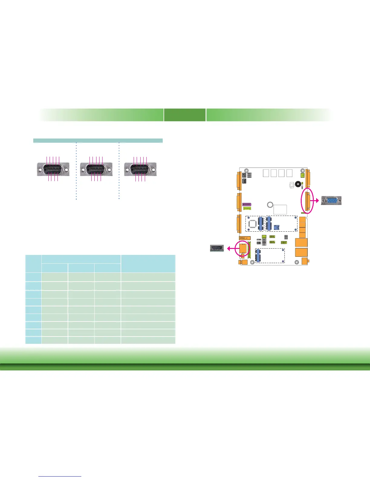
COM 1/COM 2 /COM 3/COM 4
RS232
RS422
Full Duplex
RS485
RTS-
RI-
DSR-
CTS-
6789
DCD-
TXD
RXD
DTR-
GND
1
2345
RX+
TX+
RX-
TX-
GND
12345
6789
N.C.
N.C.
N.C.
N.C.
DATA+
DATA-
12345
GND
N.C.
N.C.
N.C.
N.C.
N.C.
N.C.
6789
COM 4 (Serial) Port
This DB-9 serial port can be used as a RS232/422/485 COM port or as an isolated 8-bit DIO
via the jumper setting. Refer to “COM 4/DIO Select“ in this section for its respective configura-
tion.
8-bit DIO (4-bit in and 4-bit out)
The 8-bit Digital I/O connector provides powering-on function to external devices that are con-
nected to the connector.
Pins
COM 4 Function
DIO Function
RS232 RS422 RS485
1
DCD RX+ DATA+ DIN0A
2
RX RX- DATA- DIN0B
3
TX TX+ NC DIN1A
4
DTR TX- NC DIN1B
5
GND GND GND GND
6
DSR NC NC
DOUT0A
7
RTS NC NC
DOUT0B
8
CTS NC NC DOUT1A
9
RI NC NC DOUT1B
Graphics Interfaces
VGA Port
The VGA port is used for connecting a VGA monitor. Connect the monitor’s 15-pin D-shell cable
connector to the VGA port. After y
ou plug the monitor’s cable connector into the VGA port,
gently tighten the cable screws to hold the connector in place.
HDMI Port
The HDMI port which carries both digital audio and video signals is used to connect a LCD
monitor or digital TV that has the HDMI port.
BIOS Setting
Configure the display devices in the Chipset menu (“North Bridge Configuration” submenu) of
the BIOS. Refer to the chapter 3 for more information.
3
HDMI
The display ports consist of the following:
• 1 HDMI port
• 1 VGA port
VGA