MODEL BMG-535 GRINDER
SECTION 3 GENERAL
19
OPERATING MANUAL
APRIL 2009
Grinding & Polishing
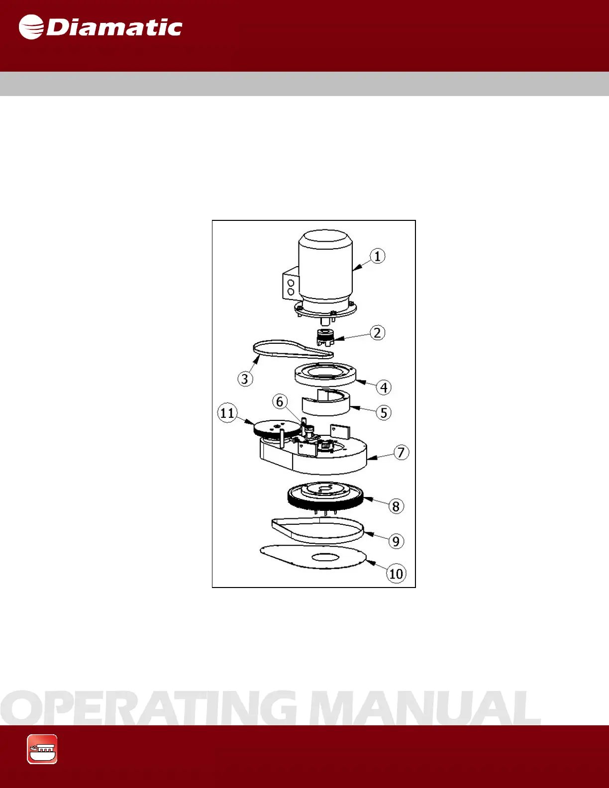
The upper part of the BMG-535 is where the drive system for the machine is
located. The rotational drive is powered through a speed reduction drive belt and
pulley system, which also gives rotation to the grinder head and drive to the center
pulley. Upper Belt (item #3) in Figure 3.4 is set using an electronic belt tension
meter at the factory and set somewhere between 200-215 Hz. The Housing Drive
belt (item #9) is also set using an electronic belt tension meter at the factory and set
somewhere between 160-170 Hz.
Fig. 3.4
1 Motor 5 Spider bearing 9 Tensioner upper belt
2 Coupling 6 Motor housing 10 Contra pulley
3 Flange motor seat 7 Center pulley
4 Motor seat 8 Upper belt
3.6 UPPE
PART