1 Introduction
ECO 9099 SOP05-5090F Rev.00 Effective Date: 12/20/18 Page 29 of 58
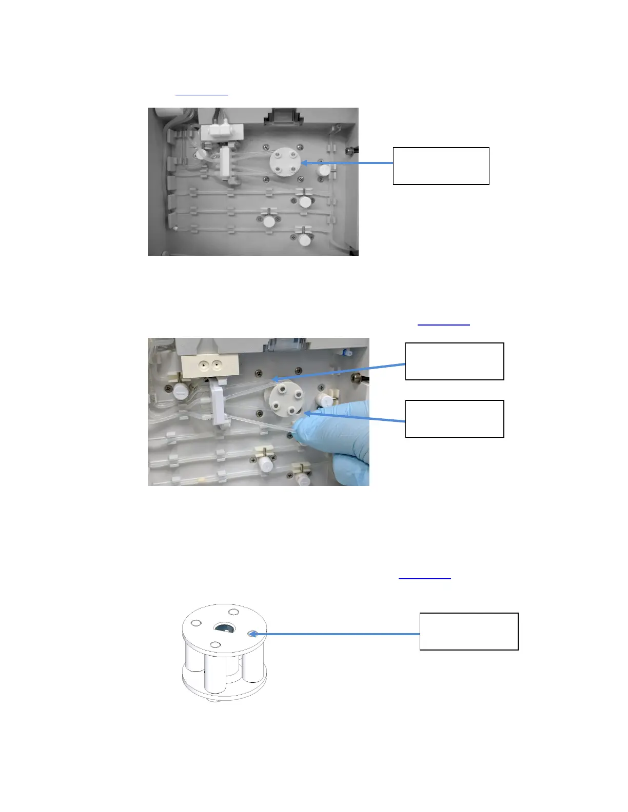
1.3.1.8. Peristaltic Pump Rotor (CN-A4014)
The Peristaltic Pump Rotor works with the Peristaltic Pump Motor to manage all fluid flow through
the analyzer. (Figure 1-37
)
Figure 1-37 Peristaltic Pump Rotor on Analyzer
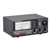
To Remove the Rotor;
1. Unwind front and back Peri-Pump tubing from the Motor shaft. (Figure 1-38
)
Figure 1-38 Unwinding Peri-Pump Tubing
2. Grasp the Rotor Assembly firmly and pull away from the instrument.
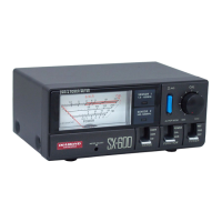
To install the Rotor Assembly;
1. Align the rotor flat interface with the flat on the motor shaft.(Figure 1-39
)
Figure 1-39 Peristaltic Pump Rotor
Front Tubing
Peristaltic
Pump Rotor
Back Tubing
Flat Surface