1 Introduction
ECO 9099 SOP05-5090F Rev.00 Effective Date: 12/20/18 Page 46 of 58
1.5. Electronics
1.5.1. Block Diagram of SmartLyte® Plus
SmartLyte
®
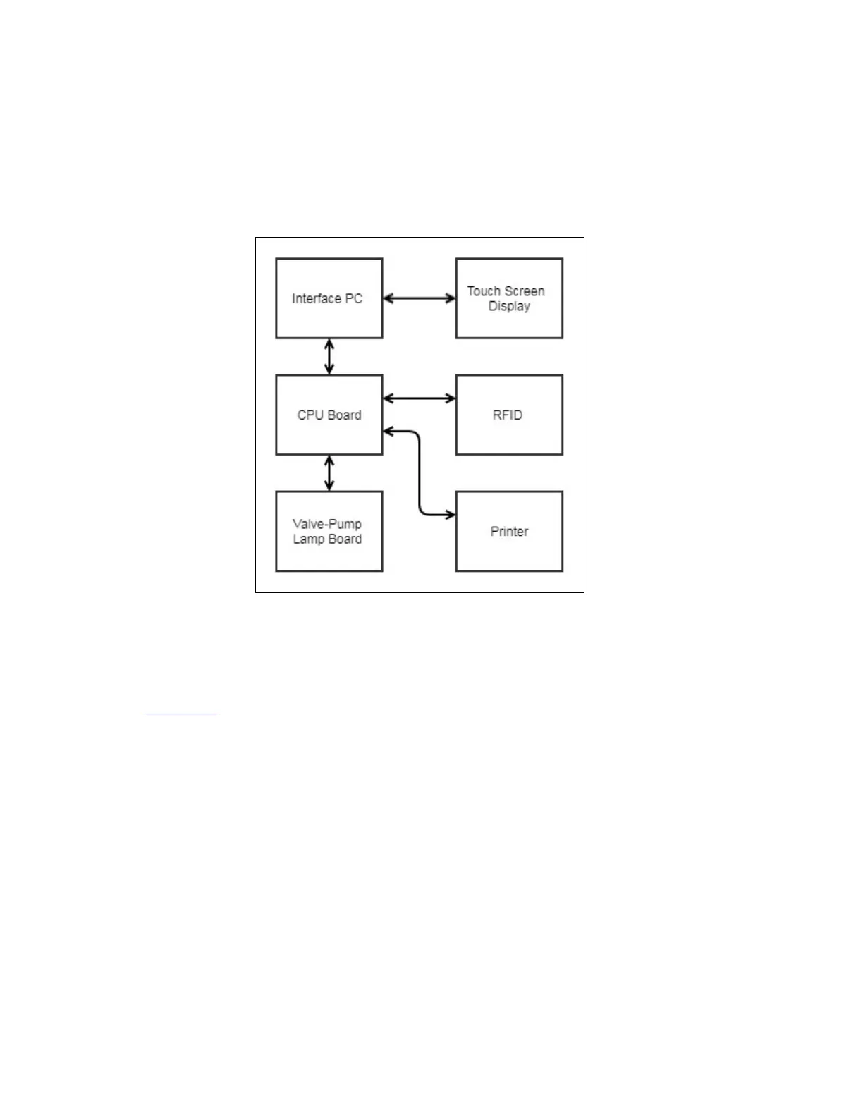
Plus consists of 2 controller boards – CPU board and interface-PC board. Both the
boards communicate over the interconnected flat ribbon cables. Figure below represents the top
level electronic design of the SmartLyte
®
Plus.
Figure 1-64 Architecture showing top level electronic design
1.5.2. CPU Board
Figure 1-64 shows CPU block diagram. CPU board is responsible for following peripherals/features:
• Pump
• Valve
• Printer
• RS232 LIS
• Lamp
• Temperature Sensor
• Sample Sensor
• Signal processing
• RFID
• Fluid pack sensor
• Door
• Buzzer
• Power distribution