1 Introduction
ECO 9099 SOP05-5090F Rev.00 Effective Date: 12/20/18 Page 31 of 58
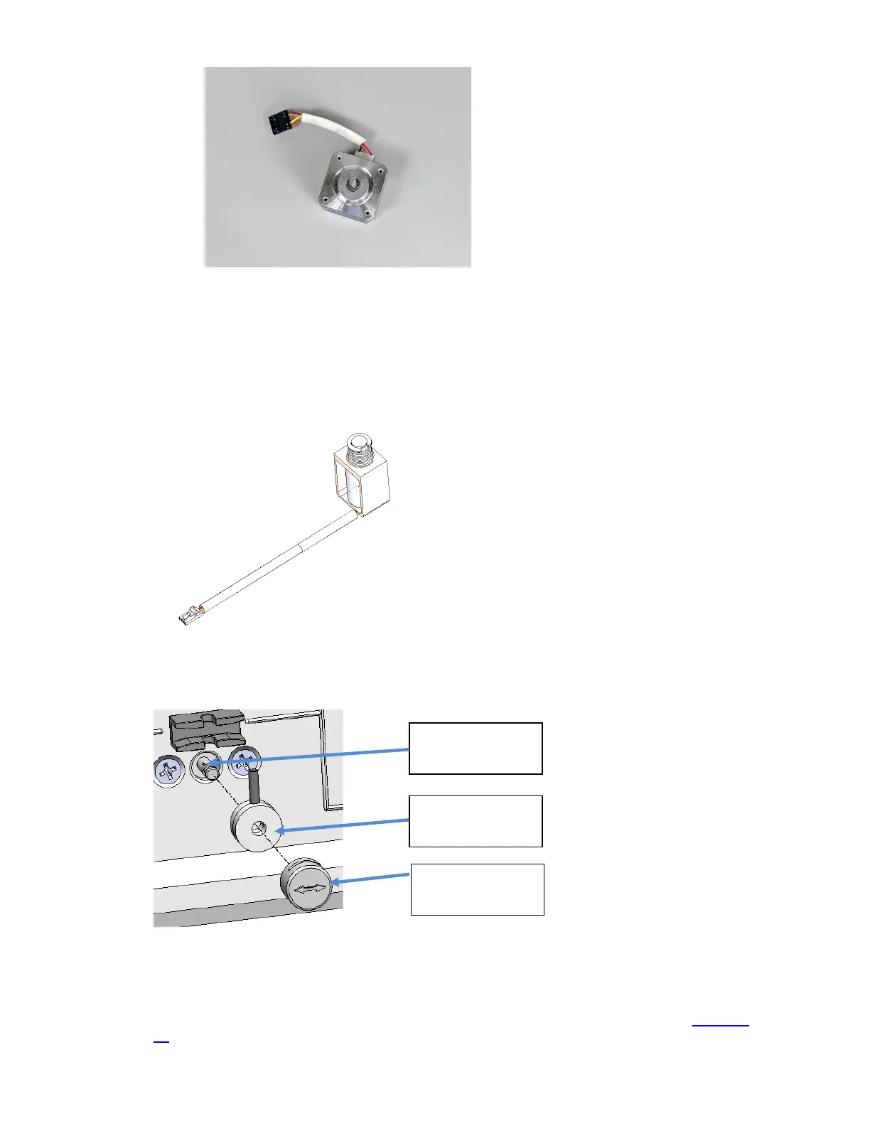
Figure 1-42 Peristaltic Pump Motor
1.3.1.10. Solenoid Valve System
The Solenoid Valve System is comprised of the solenoid valve subassembly, CN-A4015, the
crimp pin, CN-4155, and the indicator cap, CN-4018. The Crimp Pin applies pressure to the
tubing to shut off fluid flow. The Indicator Cap holds the Crimp Pin in place.
Figure 1-43 Peristaltic Pump Motor
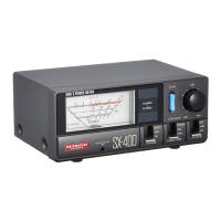
Figure 1-44 Crimp Pin, and Indicator
There are 5 solenoid valves, one each for Standard A (A), Standard B (B), Standard C (C),
Reference Solution (R), and Air (V). The removal of each solenoid valve is identical. (
Figure 1-
45)
Crimp Pin
Indicator Cap/
Opening
Motor Shaft