1 Introduction
ECO 9099 SOP05-5090F Rev.00 Effective Date: 12/20/18 Page 37 of 58
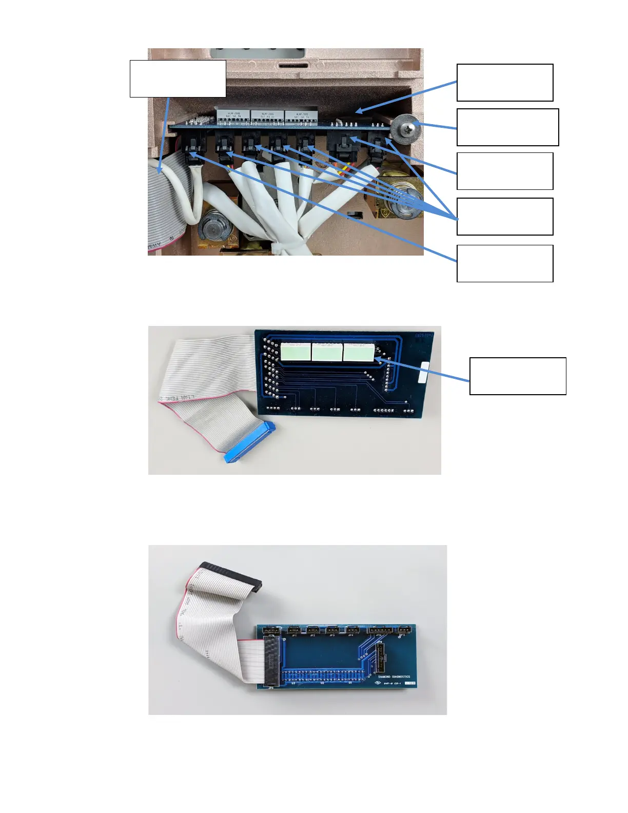
Figure1-52 Valve Board
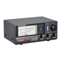
The top side of the Valve Board has three lamps that illuminate the measurement pathway
when fluids flow.
Figure 1-53 Valve Board, Top
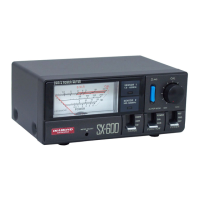
The Bottom side of the Valve Board seven connectors for the Aspiration Assembly, Solenoid
Valves and Pump Motor.
Figure 1-54 Valve Board, Bottom
Valve Board
Peri-Pump
Motor Plug
Washer & Screw to
secure Valve Board
Solenoid Valve
Plugs
Aspiration
Assembly Plug
Valve Board Ribbon
Cable and Connector
Lamps