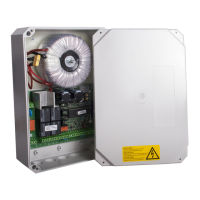
Motor control unit DCM31
11 / 35
5) Controls / Displays
[X7]
[Ta.+] +: value + / menu + / open function
[Ta.-] -: value - / menu - / close function
[Ta.F] Radio: key to teach / delete the radio in radio module mode
[Ta.M] Menu: menu selection/ display input status
a) LEDs next to the display
[X7]
Light (yellow) Light / warning light control display
radio (red) radio display for radio module mode (reception)
OUT (yellow) display output OUT [Kl.12]+[Kl.13]
b) LEDs behind terminals
[X6]
behind [KL.14]+[Kl.15] red emergency stop input
behind [KL.16]+[Kl.17] green limit switch M1 OPEN
behind [KL.17]+[Kl.18] green limit switch M1 CLOSE
behind [KL.19]+[Kl.20] green limit switch M2 OPEN
behind [KL.20]+[Kl.21] green limit switch M2 CLOSE
behind [KL.22]+[Kl.23] yellow photoelectric barrier (LS)
behind [KL.23]+[Kl.24] yellow closing edge safety device (SE)
behind [KL.25]+[Kl.26] green input A
behind [KL.26]+[Kl.27] green input B
c) Jumper [J1]
[X4]
- If a closing edge safety device is connected to the SE input (8K2 or OSE), the
jumper must be connected to SE.
- If no closing edge safety device is connected, the jumper must be connected to
NC.