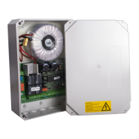
Motor control unit DCM31
7 / 35
4) Connections
a) Terminals
[X2], [X6]
Only work on the controls after it has been disconnected from the power
supply and has been ESD-compatibly earthed!
- 230 volt mains voltage can be applied to [Kl.1]..[Kl.4] and [Kl.30], [Kl.31]. Potentially
fatal danger!
- Never connect mains voltage to [Kl.5].. [Kl.29].
- Failure to comply causes immediate destruction of the controls and the guarantee
expires!
- Signal and motor cables (e.g. pulse, open, stop, close...) must not exceed a length
of max 30 m! This does not apply to the mains supply cable.
[Kl.1]+[Kl.2] mains voltage 230V / AC
Terminal 1 = N conductor
Terminal 2 = L conductor
- Comply with the local safety regulations and applicable VDE regulations.
- We recommend installation of a motor protecting switch in the mains supply cable.
[Kl.3]+[Kl.4] light / warning light 230 V / AC output, max. 500W
Terminal 3 = N conductor
Terminal 4 = L conductor (L= connected)
- The light/warning light function is set via [M.b2].
- The switched status is displayed by the yellow “Light” LED [X7].
[Kl.5]+[Kl.6] Motor M1, 24V / DC output
Terminal 5 = “-“ for opening
Terminal 6 = “+“ for opening
- Motor 1 is the main motor and is also used as the active leaf motor.
- If the control unit is run with one motor only [M.C1], this must be connected to M1.
- In 2 motor mode, for opening motor 1 starts at the same time or before motor 2
[M.C3] and for closing motor 1 starts at the same time or after motor 2 [M.C2].
- After the control unit has been installed and the first pulse command is given, the
direction of travel must be “OPEN”.
- If the drive unit, despite bar running upwards in the 7 segment display, starts up in
the “CLOSE” direction the connection wires [Kl.5]+[Kl.6] must be switched over.
- The control unit learns the maximum motor current for each direction of travel.
- Motor adjustments are made in [M.A1]..[M.A8].
[Kl.7]+[Kl.8] Motor M2, 24V / DC output
Terminal 7 = “-“ for opening
Terminal 8 = “+“for opening
- After the control unit has been installed and the first pulse command is given the
direction of travel must be “OPEN”.
- If the control unit is operated with one motor only [M.C1], it must be connected to
M1.
- In 2 motor mode motor 2 starts in opening at the same time or after motor 1 [M.C3]
and in closing motor 2 closes at the same time or before motor 2 [M.C2].