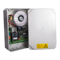
Motor control unit DCM31
31 / 35
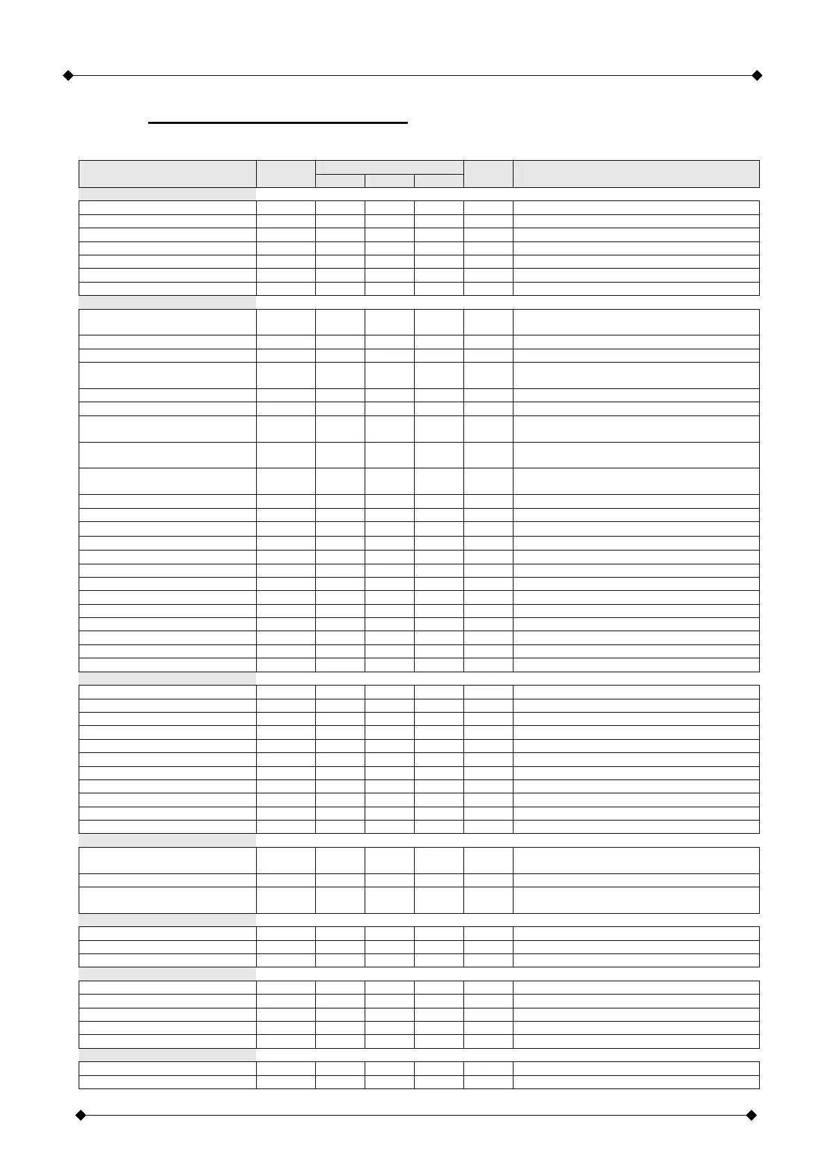
10) Technical Specifications
The control unit may only be used if the technical specifications are observed!
Limit values
Parameter Symbol
Min. Typical Max.
Units Test condition
Power supply
Mains voltage U
mains
190 230 250 V
AC
At terminals 1 / 2
Mains frequency F
mains
48 50 52 Hz
Secondary voltage U
Sec
18 24 29 V
AC
at terminals 32 / 33 at rest / at full load
Internal logic voltage U
V
4.8 5.0 5.2 V
Current input when idle I
R
40 mA terminals 32 / 33, no loads / cards
Power input P
Prim
2.0 2.5 VA terminals 32 / 33, no loads / cards
Start time voltage / 1
st
start t
Start
2.5 3.5 s @ U
Secondary
= 24V
AC
Inputs
Emergency stop not actuated
(closed)
U
EMERclosed
0.0 0.5 V
Via terminals 14 / 15
Emergency stop actuated (open) U
EMERopen
1.0 V Terminal 15 / 0V
Emergency stop current (closed) I
EMER
170 200 mA Via terminals 14 / 15
ES open / close not actuated
(closed)
U
ESclosed
0.5 V
Terminal 16, 18, 19, 21 against 0V
ES open / close actuated (open) U
ESopen
4.5 V Terminal 16, 18, 19, 21 against 0V
ES open / close current (closed) I
ES
0.5 1.0 mA Via terminals 16/17, 18/17, 19/20, 21/20
Photoelectric barrier not actuated
(close)
U
Lsclosed
0.5 V
Terminals 22 / 23
Photoelectric barrier actuated
(open)
U
Lsopen
4.5 V
Terminal 22 against 0V
Photoelectric barrier short-circuit
current
I
LSin-0
0.5 1.0 mA
Via terminals 22 / 23
Photoelectric barrier reaction time t
LS-1
25 50 ms Time LS-command until motor switched
Photoelectric barrier reset time t
LS-0
250 350 ms
SE (8K2) not actuated
R
SE12-0
6.0 8.2 13.0
KΩ
terminals 23 / 24
SE (8K2) actuated
R
SE12-1
17.0 5.5
KΩ
terminals 23 / 24
SE (OSE) level, release U
SE12OSE-0
4.0 1.0 V terminals 23 / 24
SE (OSE) frequency f
SE12OSE-0
0.5 1.0 2.0 KHz terminals 23 / 24
SE reaction time t
SE12-1
25 50 ms At 8K2 or OSE
SE reset time t
SE12-0
250 350 ms
A / B not actuated (open) U
O-AB
4.5 V At terminals 25 / 26, 27 / 26
A / B actuated (closed) U
CI-AB
0.5 V At terminals 25 / 26, 27 / 26
A / B pulse duration (debounce) T
AB
30 35 50 ms
NF Low level V
NFLow
0.7 V @ U
V
= 5.0V, Pin14 of BL1
NF High level V
NFHigh
3.5 V @ U
V
= 5.0V, Pin 14 of BL1
Outputs
Voltage 12V output U
12V
11.5 12.0 12.5 V
DC
Full load / idle mode
Current 12V output I
12V
40 mA
Voltage 24V output U
24V
20 32 39 V
AC
Full load / idle mode
Current 24V output I
24V
200 mA
Motor current I
Motor
1.0 11.0 A
Current allowance value I
Zug
0.4 5.0 A Adjustable via menu
Motor running time t
Mot
1 100 S
Motor operating time ED 25 % At maximum motor current, max running time
OUT maximum voltage U
Out
30 V At terminals 12 / 13
OUT maximum current I
Out
4 A At terminals 12 / 13
Warning light output P
Warn
500 W At terminals 3 / 4
Radio (radio module mode)
Receiver data
Depending on plug-in card radio module /
receiver
Coding systems 12- / 18-Bit linear, Keeloq (others on request)
Teaching capable transmission
buttons
N
transmitter
40 Each
Transmission buttons
Ambient conditions
Operating temperature T
oper
-20 +50 °C In normal installed position
Storage temperature T
stor
-25 +80 °C
Relative air humidity RH 20 90 % No condensation permitted!
Printed circuit board
Controller frequency f
Cont
4.19 MHz Internal PLL at 16.76MHz
Length L
LP
110 mm
Width B
LP
166 mm
Height H
LP
45 mm
Weight m
LP
320 g Without radio module, no other plug-in card
Housing
Length L
Hous
255 mm Without cable entry
Width B
Hous
176 mm