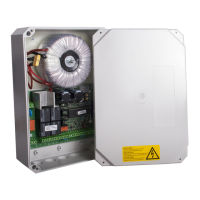
Motor control unit DCM31
6 / 35
The motor output / motor speed can be reduced over the last part of the travel path so
that the gate does not hit the end stop at full speed.
Electricity stop
The control unit monitors the motor current for obstacle detection. You can choose
how the control unit reacts if the set value is exceeded.
Partial opening
The gate can be specifically moved to a previously selected position between the limit
switches (e.g. to allow people through).
a) Abbreviations used in the instructions
[Bl.1] = 15 pin slot for the radio module
[Bl.2] = 2x10 pin slot for 1 or 4 channel radio receiver
[J1] = Jumper for safety equipment (SE)
[Kl.1]..[Kl.33] = Reference to terminals
M1, M2 = Motor 1 or Motor 2
[M.A0]..[M.A9]
[M.b0]..[M.b9]
[M.C0]..[M.C9]
[M.d0]..[M.d9] = Menu items A0 to d9
[Ta.+] = “+” pushbutton in the control panel under the 7 segment display
[Ta.-] = “-” pushbutton in the control panel under the 7 segment display
[Ta.F] = “Radio” pushbutton in the control panel under the 7 segment display
[Ta.M] = “Menu” pushbutton in the control panel under the 7 segment display
[X1]..[X10] = Reference to figure in the separate graphic overview
{F0}..{F9} = Radio module function, shown in the display
{Er.00}..{Er.29} = Error/fault message, shown in the display