Horizontal-Schrumpfgerät
Horizontal Shrinking Device
HS 1100-P
Copyright © Diebold 2017-04 Ersteller: kh
18. Initial Set-Up of the HS 1100-P
18.1. Connecting the device
To ensure that the unit is not damaged during the unpacking process,
unload the unit with the top facing up. Do not hold the unit housing by
the coil.
Connect the power cord to the power supply. Make sure that the main power switch
while the unit is off. Through the operation of the main switch, the device is now ready
for operation. The LC display will show "Diebold".
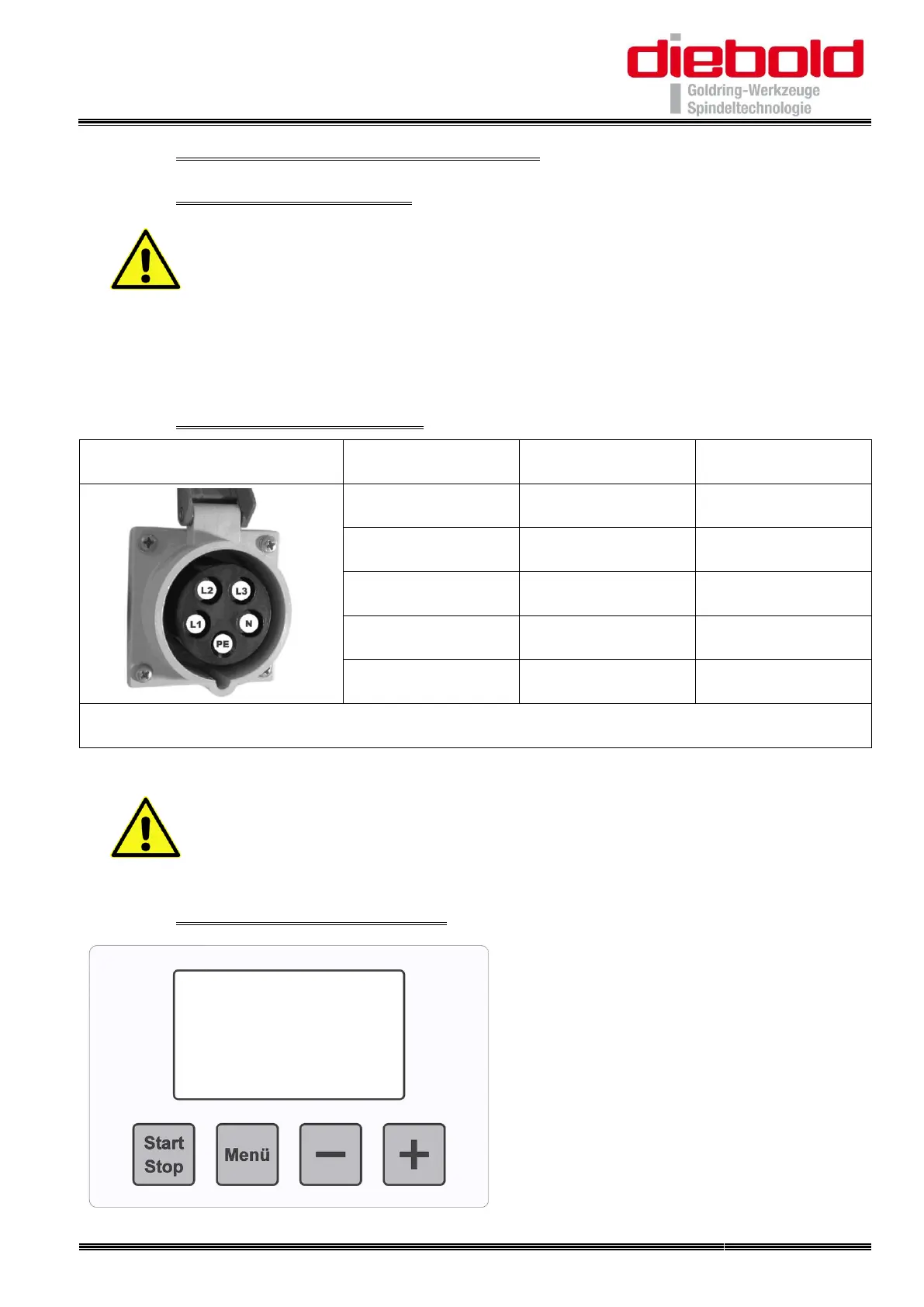
18.2. On-site socket and fuse
The rated voltage between the phases is 3x400V (-10/+10%)
Always connect the neutral wire N and protective earth PE !
If a ground fault circuit-breaker is used to secure the CEE socket, it
must be a 4-pin model and according to DIN VDE 0100 (part 530) for
frequency converters of type B (all-current-sensitive).
18.3. Controls of the HS 1100-P